Supercharge Your Innovation With Domain-Expert AI Agents!

Valve with built-in heater

A heater and piston technology, applied in valve operation/release device, valve device, valve heating/cooling device, etc., can solve problems such as inability to withstand high temperature

Inactive Publication Date: 2010-03-03
FUJIKIN INC
View PDF1 Cites 5 Cited by
  • Summary
  • Abstract
  • Description
  • Claims
  • Application Information

AI Technical Summary

Problems solved by technology

[0004] The valve with a built-in heater in Patent Document 1 mentioned above is a valve that can be heated to 130 to 150°C, and has the problem that it cannot withstand high temperatures exceeding 200°C (for example, 450°C).

Method used


Image

  • Valve with built-in heater
  • Valve with built-in heater
  • Valve with built-in heater

Examples


Embodiment Construction

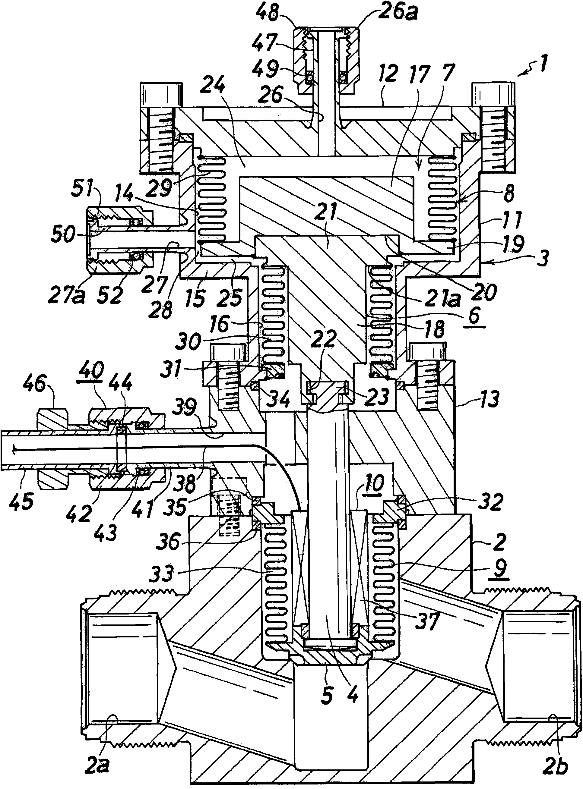
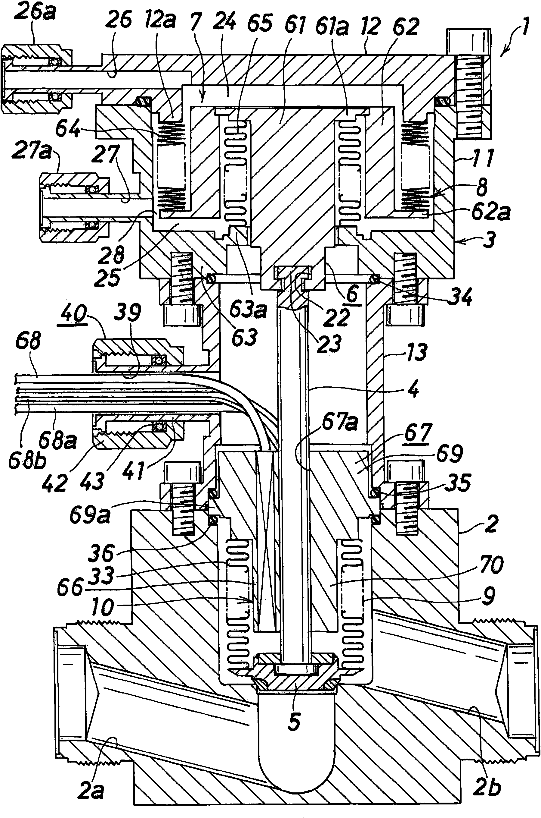
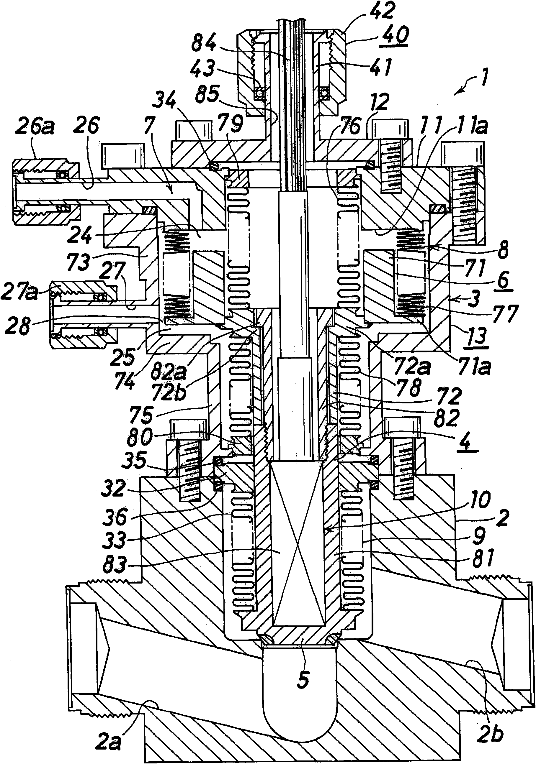
[0073] Hereinafter, embodiments of the present invention will be described with reference to the drawings. In the following description, up, down, and left and right refer to up, down, and left and right in each figure.

[0074] The first embodiment of the valve 1 with a built-in heater based on the present invention is as follows figure 1 As shown, it has: a valve body 2 provided with a fluid inflow passage 2a and a fluid outflow passage 2b; a housing 3 fixed on the upper end of the valve body 2; the upper part of the valve body 2 is freely movable up and down, and the upper part is in the housing 3 The valve rod 4 inside; the valve core 5 that is suspended and supported on the lower end of the valve rod 4, and the fluid inflow passage 2a is opened and closed along with the up and down movement of the valve rod 4; the piston 6 fixed on the upper end of the valve rod 4; the piston 6 The piston driving mechanism 7 that moves up and down; the piston sealing mechanism 8 that sea...


PUM


Abstract

A valve with a built-in heater usable even under a high temperature exceeding 200 DEG C. A piston drive means (7) has an upper compressed air introduction chamber (24) for moving a piston (6) downwardand a lower compressed air introduction chamber (25) for moving the piston (6) upward. A piston seal means (8) includes an upper bellows (29) for sealing the upper compressed air introduction chamber(24) and a lower bellows (30) for sealing the lower compressed air introduction chamber (25).

Description

technical field [0001] The present invention relates to a valve with a built-in heater, and more particularly, to a valve with a built-in heater to be used under high temperature conditions such as over 200°C. Background technique [0002] As a valve with a built-in heater, the valve disclosed in Patent Document 1 includes: a valve body provided with a fluid passage; a case provided on the upper part of the valve body; a valve stem that moves a valve body for opening and closing the fluid passage up and down; A piston that can move up and down is arranged in the casing and is fixed on the valve stem; a piston driving mechanism that moves the piston up and down; a heater that heats the vicinity of the valve core. The heater is a member for preventing solidification of the gas flowing to the valve, and can be heated to 130 to 150°C. [0003] Patent Document 1: Japanese Patent Application Laid-Open No. 7-198063 [0004] The valve with a built-in heater of Patent Document 1 de...

Claims


Application Information

Patent Timeline
Patent Type & Authority Applications(China)
IPC IPC(8): F16K31/122F16K49/00
CPCF16K41/10F16K49/002Y10T137/6606F16K31/122F16K49/00
Inventor 谷川毅山路道雄药师神忠幸福地仁石桥圭介
Owner FUJIKIN INC
Features
  • R&D
  • Intellectual Property
  • Life Sciences
  • Materials
  • Tech Scout
  • Unparalleled Data Quality
  • Higher Quality Content
  • 60% Fewer Hallucinations
Learn More