Airborne single baseline Doppler-phase difference direction finding method

A phase difference and Doppler technology, applied in direction finders using radio waves, etc., can solve problems such as the inability to install receiving array elements, large errors in the angle of arrival, and limited estimation accuracy

Active Publication Date: 2012-05-23
CHINESE AERONAUTICAL RADIO ELECTRONICS RES INST
View PDF0 Cites 0 Cited by
  • Summary
  • Abstract
  • Description
  • Claims
  • Application Information

AI Technical Summary

Problems solved by technology

[0004] In actual use, the method of combining long and short baselines has two limitations: First, for broadband receiving array elements, such as the receiving range is 2GHz-8GHz, the lowest receiving frequency determines the physical size of the array element, while the highest The receiving frequency determines the baseline length of the short-baseline interferometer, making it impossible to install two receiving array elements within the half-wavelength range; When the phase difference of the baseline interferometer is defuzzified, the wrong ambiguity number may be obtained, resulting in a large error in the estimation of the angle of arrival
[0006] For the multi-baseline defuzzification method, due to the need for multi-dimensional integer search, there is a problem of relatively large amount of calculation

Method used


Image

  • Airborne single baseline Doppler-phase difference direction finding method
  • Airborne single baseline Doppler-phase difference direction finding method
  • Airborne single baseline Doppler-phase difference direction finding method

Examples


Embodiment Construction

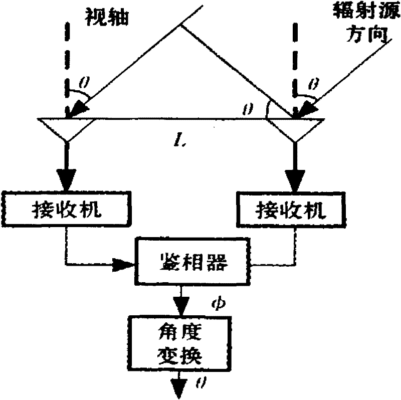
[0047] It can be seen from formula (1) that the azimuth angle θ of the radiation source can be obtained by changing the angle of the phase information φ taken out of the phase detector.

[0048] 2. The ratio of the Doppler rate of change between the two array elements

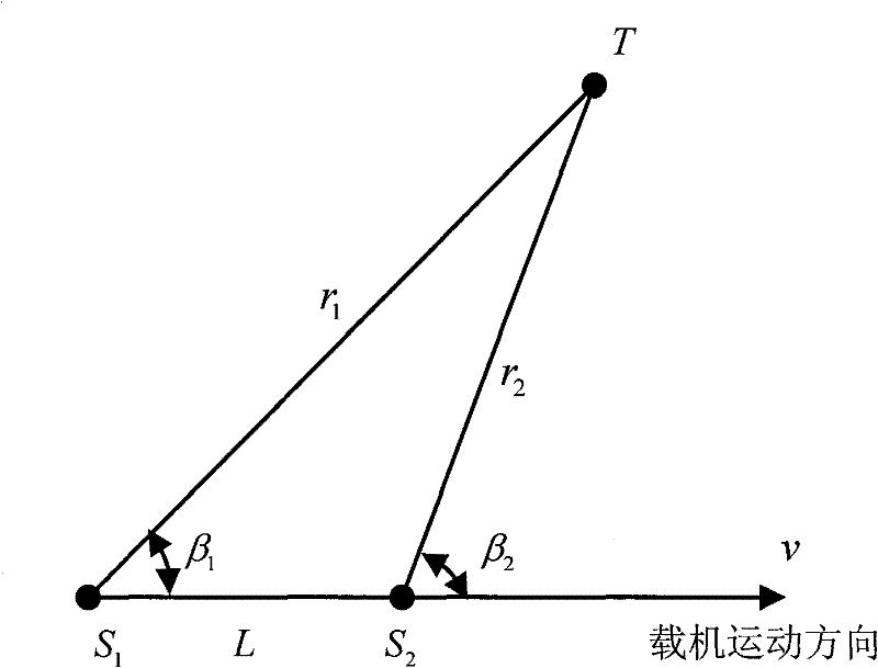
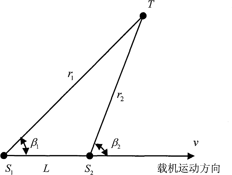
[0049] The geometric relationship of the single-baseline Doppler-phase-difference direction-finding array applied to airborne is as follows: figure 2 shown. Assuming that the target is stationary or moving at a low speed, when the carrier aircraft moves at a constant speed v, the expressions of the Doppler frequency shift change rates at the two array elements are respectively:

[0050]

[0051]

[0052] In the formula: r i is the radial distance; v t is the tangential velocity.

[0053] Its ratio is:

[0054]

[0055] And by the law of sine, the ratio of the radial distance between the two array elements can be obtained as:

[0056] r 2 ...


PUM


Abstract

The invention discloses an airborne single baseline Doppler-phase difference direction finding method by which an entire cycle solution of a radial distance can be directly obtained through comprehensively utilizing the relation among a speed vector equation, a Doppler frequency shift and a change rate, therefore, an entire cycle value of a path difference between radial distances of two adjacentarray elements of single baseline can be obtained. The path difference is entirely determined after the value of a non-entire cycle part of the path difference is determined by further utilizing a phase difference. Hence, under the condition that the length of the baseline is determined, the direction of an object can be directly obtained according to a trigonometric function relationship. The invention has a series of advantages of low installation requirement, short measuring time, suitability for bandwidth detection, and the like.

Description

technical field [0001] The invention belongs to the technical field of radio measurement, and specifically relates to a method for realizing airborne single-baseline, ambiguity-free, and high-precision direction finding by comprehensively utilizing velocity vector equations, Doppler frequency shifts and rate-of-change relationships, and phase difference measurement techniques. Background technique [0002] Phase interferometry is a direction finding method with high measurement accuracy, which has been widely used in active and passive detection systems. Since the phase interferometer can only measure the phase difference in a single value in the range of [-π, π], and the direction finding error is inversely proportional to the baseline length, therefore, the single baseline phase interferometer always has direction finding accuracy and the contradiction between the maximum unambiguous angle. [0003] In order to solve this contradiction, it is usually necessary to adopt a ...

Claims


Application Information

Patent Timeline
Patent Type & Authority Patents(China)
IPC IPC(8): G01S3/02
Inventor 郁涛
Owner CHINESE AERONAUTICAL RADIO ELECTRONICS RES INST
Why Eureka
Try Eureka