Six-claw double-linkage self-centering chuck

A self-centering chuck and linkage technology, applied in the direction of chucks, etc., can solve the problems of complex system and internal structure, small contact area at three points, uneven force on parts, etc., to shorten the production preparation period, and the structure is simple and compact. , Reduce the effect of card deformation

Inactive Publication Date: 2010-09-15
SICHUAN AEROSPACE LONG MARCH EQUIP MFG CO LTD
View PDF6 Cites 18 Cited by
  • Summary
  • Abstract
  • Description
  • Claims
  • Application Information

AI Technical Summary

Problems solved by technology

[0004] Three-jaw self-centering chucks are roughly divided into several structural types according to their transmission methods: wire type, wedge type, lever type, and helical tooth type. The working principle is simple and reliable, and they all use various transmission methods to realize three-jaw The synchronous centripetal movement, and then realize the centering clamping of the parts, its main disadvantage is that the three-point contact area between the claw body and the parts is small and scattered, resulting in uneven force on the parts and large radial deformation
Two-two floating of the six jaws can not only completely position but also ensure reliable contact between each jaw and the workpiece, but its system and internal structure are relatively complicated.

Method used


Image

  • Six-claw double-linkage self-centering chuck
  • Six-claw double-linkage self-centering chuck
  • Six-claw double-linkage self-centering chuck

Examples


Embodiment Construction

[0019] The present invention will be further described in detail below in conjunction with the accompanying drawings and specific embodiments.

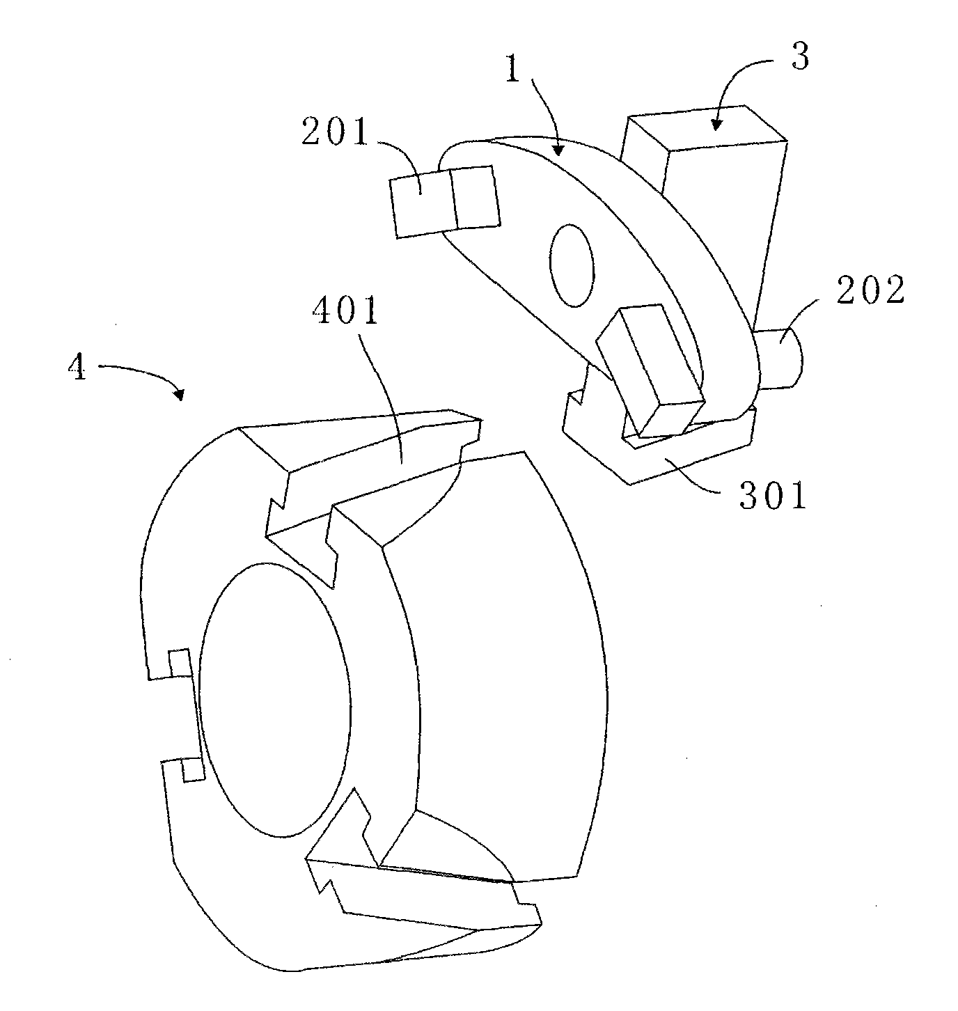
[0020] Such as Figure 1 to Figure 7 As shown, a six-jaw two-linkage self-centering chuck includes a front flange 6, a front cover 7, a bottom jaw 5, a transmission assembly, a round wedge 4, a rear end cover 8, and a rear flange 9; After the end covers 7 and 8 are mutually positioned, they are connected and fixed by screws. The front and rear flanges 6 and 9 are fixedly connected with the front and rear end covers 7 and 8 respectively after being positioned. To the straight groove 801;

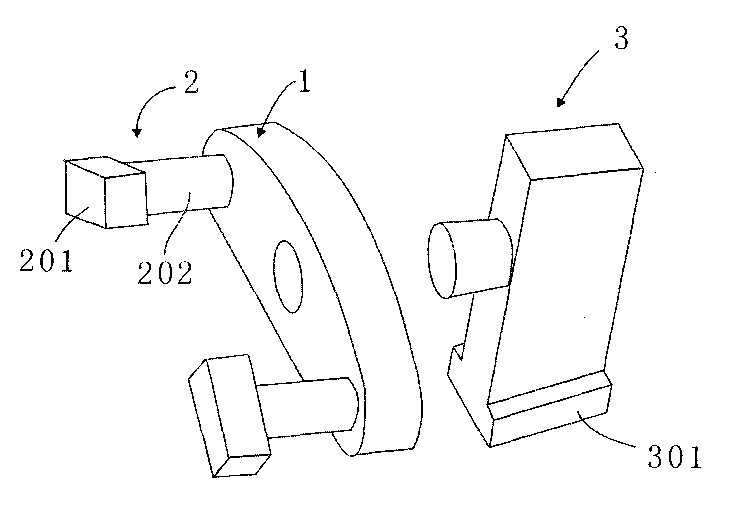
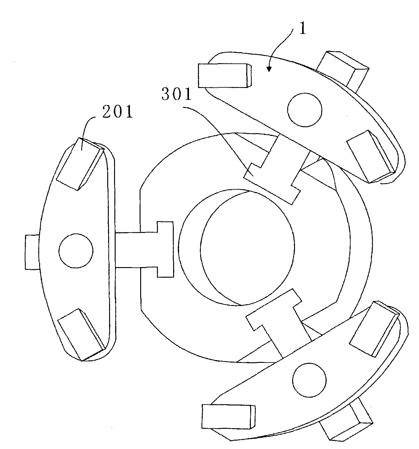
[0021] Such as figure 1 As shown, the transmission assembly is composed of a first slider 2, a floating lever 1 and a second slider 3, wherein the floating lever 1 is in the shape of a segment, its left and right ends are rounded, and the central angle corresponding to the segment is less than 180°. One end of the first slider 2 is a cylindrical p...


PUM


Abstract

The invention discloses a six-claw double-linkage self-centering chuck. The chuck comprises a transmission assembly installed between a front end cover and a back end cover, wherein the transmission assembly is formed in a way that a floating lever rod is hinged with a first sliding block and a second sliding block; one end of the first sliding block is a cylindrical pin, the other end of the first sliding block is a rectangular sliding block, the lower end of the second sliding block is an oblique T-shaped boss, the rectangular sliding block of the first sliding block is embedded in straight groove behind bottom claws to be meshed with the bottom claw, the oblique T-shaped boss at the lower end of the second sliding block is embedded in three oblique T-shaped grooves uniformly distributed in a round wedge in the circumferential direction to be meshed with the round wedge, and simultaneously an upper rectangular end is embedded in three radial straight grooves of the back end cover to be matched with the back end cover; the round wedge is assembled in the inner hole of the back end cover to slide freely in the axial direction; and the six bottom claws are respectively inserted in six radial T-shaped grooves uniformly distributed in the circumferential direction of the front end cover, and are subject to mesh type transmission by the transmission assembly. The chuck can realize favorable centering and clamping effects on rotational parts, and can effectively reduce the chucking deformation of low-rigidity thin-wall parts, thereby playing active roles in promoting and implementing process standardization.

Description

technical field [0001] The invention relates to a centering device for a rotary part on a metal cutting machine tool, in particular to a six-claw two-linkage self-centering chuck. Background technique [0002] The concrete structure of existing centering chuck roughly has the following several kinds at present: [0003] 1. Three-jaw self-centering chuck [0004] Three-jaw self-centering chucks are roughly divided into several structural types according to their transmission methods: wire type, wedge type, lever type, and helical tooth type. The working principle is simple and reliable, and they all use various transmission methods to realize three-jaw The synchronous centripetal movement of the claw body realizes the centering clamping of the parts. Its main disadvantage is that the three-point contact area between the claw body and the parts is small and scattered, resulting in uneven force on the parts and large radial deformation. Although the workpiece deformation prob...

Claims


Application Information

Patent Timeline
Patent Type & Authority Applications(China)
IPC IPC(8): B23B31/16
Inventor 杨振宇张永健
Owner SICHUAN AEROSPACE LONG MARCH EQUIP MFG CO LTD
Why Eureka
Try Eureka