Freeze and shock proof turnout

A turnout and turnout conversion technology, applied in roads, tracks, buildings, etc., can solve the problems of turnout function failure, point rail movement not in place, energy consumption, etc., reduce shock vibration and noise, increase turnout life, and eliminate harmful spaces Effect

CN101851881BInactive Publication Date: 2012-02-01HEFEI BOPU HIGH TECH
0 Cites 2 Cited by

Patent Information

Authority / Receiving Office
CN · China
Patent Type
Patents(China)
Current Assignee / Owner
Publication Date
2012-02-01
Estimated Expiration
Not applicable · inactive patent

Smart Images

  • Figure 1
    Figure 1
  • Figure 2
    Figure 2
  • Figure 3
    Figure 3
Patent Text Reader

Abstract

The invention relates to a freeze and shock proof turnout which comprises a base, a ram, a straightaway transition rail, a turnout transition rail, a drive device and a ram locking device, wherein the straightaway transition rail and the turnout transition rail are arranged on the ram. The freeze and shock proof turnout is characterized in that the straightaway transition rail and the turnout transition rail which are arranged on the ram in parallel move on the base through the ram to finish turnout conversion, and the ram is locked through a positioning device. The freeze and shock proof turnout has the advantages that because the connection between the transition rails and steel rail joints at both ends of the transition rails is smooth and has small gaps, clearance spaces in medium andlow speed turnouts at present are eliminated; a high-strength precise positioning and locking device is adopted, which ensures that a train is stable and safe during passing the turnout, and impact shocks and noise between wheels and rails are greatly reduced, thus the train can quickly and safely pass the turnout without reducing the speed; and meanwhile, the drive device is arranged in the ram to thoroughly eliminate influences caused by snow and ice in winter on the turnout, thus a snow and ice thawing device does not need to be arranged in the turnout so as to reduce the investment, save energy and protect the environment. The freeze and shock proof turnout is widely applied to medium and low speed railways and urban metro and light rail routes.
Need to check novelty before this filing date? Find Prior Art

Description

technical field

[0001] The invention relates to a turnout device used on a railway track line, in particular to an antifreeze and shockproof railway safety turnout. Background technique

[0002] At present, moveable turnouts are commonly used on railways, and the switch is realized by moving the switch rail between the straight track and the switch track. In winter, when snow accumulates, it is very easy to cause ice between the switch rail and the basic rail, resulting in improper movement of the switch rail. , so that the turnout function fails to cause accidents; the current solution is to install electric heating devices on the switch rail and the basic rail to melt the ice, which not only requires a large investment, but also consumes a lot of energy. In addition, in the current medium and low-speed turnouts, there are still harmful spaces such as turnout ditch, and the train has to slow down when passing the turnout, which restricts the running speed of the train when ...

Examples

Embodiment 1

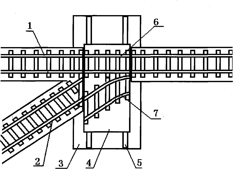
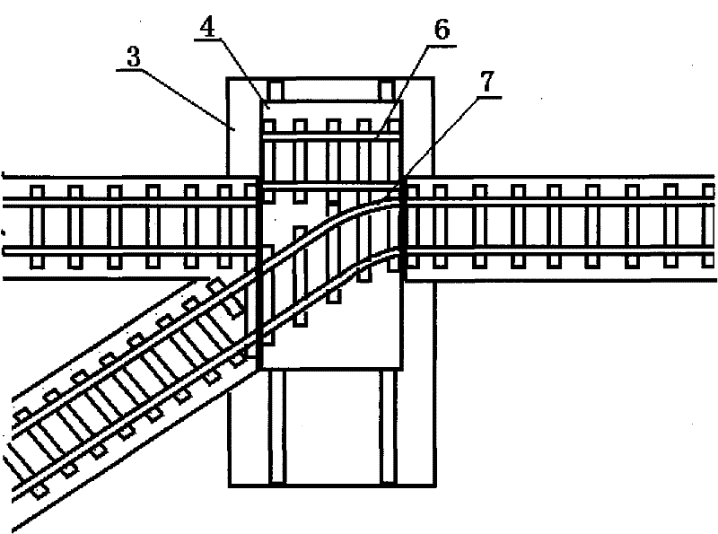
[0029] figure 1 As shown in , the base 3 on one side of the ram 4 is provided with a straight rail, and the other side is provided with a straight rail 1 and a branch rail 2; Transition rail 7; Motor 8 and screw 9 of ram driving device are provided in ram inner space (see Figure 2-1 ), one end of the screw is located in the screw thread fixedly arranged in the boss 10 on the base, the other end of the screw is connected to the motor shaft or the motor reduction device, and the driving device is controlled by a travel switch or a pressure sensor arranged on the ram or the boss to reciprocate journey.

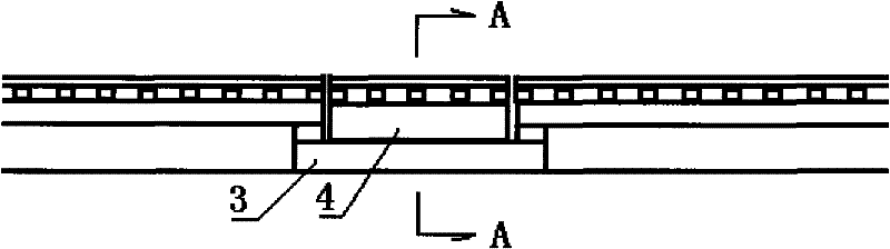
[0030] image 3 As shown in , the two ends of the straight transition rail 6 and the branch transition rail 7 arranged side by side on the ram are fixedly installed on the ram, and at the same time, there are seamless joints 11 in the straight transition rail and the branch transition rail, eliminating the need for weather and seasonal changes. Thermal expansion and contracti...

Embodiment 2

[0038] Figure 5 As shown, a positioning device is provided between the ram 3 and the base 4. The positioning device is composed of a positioning sleeve 13, a positioning sliding shaft 14, a sliding shaft sleeve 15 and a driving device. At the same time, the positioning sleeve or the sliding shaft located in the positioning sleeve 14 The outer end is provided with a travel switch or a pressure sensor to control the operation of the sliding shaft. In the sliding shaft sleeve or at the inner end of the sliding shaft in the sliding shaft sleeve, a travel switch or a pressure sensor is set to control the reset stroke of the sliding shaft; in the sliding shaft sleeve 15 or at the inner end of the sliding shaft in the sliding shaft sleeve, there is also a Pressure sensor that controls the ram drive.

[0039] In the application, when it is necessary to change the traffic state of the turnout, the power supply of the driving device in the positioning device is first turned on in reve...