Pile-forming drilling tool for screw pile and pile-forming construction method thereof

A screw pile and drilling tool technology, which is applied in the direction of drill bits, drill pipes, drill pipes, etc., can solve the problems of pile body mud inclusion, pile body quality impact, high construction requirements, etc., to achieve faster pile formation, higher pile quality, The effect of simple construction process

Inactive Publication Date: 2010-10-20
彭桂皎
View PDF8 Cites 17 Cited by
  • Summary
  • Abstract
  • Description
  • Claims
  • Application Information

AI Technical Summary

Problems solved by technology

But its shortcomings: 1. During the construction process, the drill pipe must be suspended when it is converted from rotation to straight lifting, and the pumping of concrete must be suspended during the suspension process, which affects the construction speed.
2. When directly lifting the drill pipe, if it encounters quicksand or soft soil, it will easily cause hole collapse, and the drill pipe cannot be directly lifted. The resistance of the straight bar section is relatively large, and it is easy to bring out part of the soil between the screw teeth, which leads to the limitation of the application of this technology
3. After the pumping of the concrete, the drill pipe is lifted to the ground and part of the soil is taken out and easily falls into the unsolidified pile hole concrete. If it is not cleaned in time, the placement of the reinforcement cage will easily cause the phenomenon of mud in the pile body, and the quality of the pile body will be affected. influences
4. The boundary between the straight rod section and the threaded section of the pile is judged by the eyes of the construction operator. Whether it enters the boundary section depends on human judgment, which is prone to errors, resulting in deviations from the design requirements
But its disadvantages: 1. It must be suspended during the process of pumping concrete into piles, which affects the construction speed, and the process is complicated, and the conversion between synchronous and asynchronous requires relatively high construction requirements
2. If saturated clay and soft soil are encountered during the construction process, due to the necking of the soil when the drill pipe is lifted up, the resistance of the straight rod section is relatively large, and the part between the screw teeth is easy to be taken out Soil, leading to limitations in the application of this technology
3. Because the soil has a certain amount of rebound, the reverse rotation of the lifted drill pipe makes the soil easy to form a shallow screw, causing the diameter of some soil holes in the straight rod section to shrink, which affects the quality of the pile.
4. After the concrete is pumped, the soil is easy to fall into the unsolidified pile hole concrete. If it is not cleaned up in time, the placement of the reinforcement cage will easily cause the phenomenon of mud in the pile body, and the quality of the pile body will be affected.
5. The boundary between the straight rod and the threaded section of the pile is judged by the eyes of the construction operator. Whether it enters the boundary section depends on human judgment, which is prone to errors, resulting in deviations from the design requirements.
[0005] Patent 200710063983.3 also discloses a two-way spiral extruded and expanded pile construction method and a two-way helical closed extruded and expanded drill bit. There are following disadvantages in the construction of soft soil and quicksand soil: 1. The short drill bit is used to extrude and expand the hole twice. The drill pipe has no wall protection function, and the formed holes are prone to collapse

Method used


Image

  • Pile-forming drilling tool for screw pile and pile-forming construction method thereof
  • Pile-forming drilling tool for screw pile and pile-forming construction method thereof
  • Pile-forming drilling tool for screw pile and pile-forming construction method thereof

Examples


Embodiment Construction

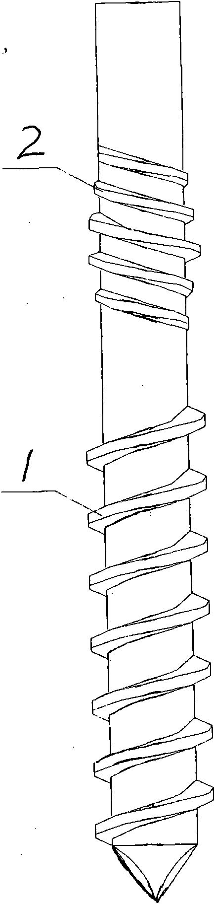
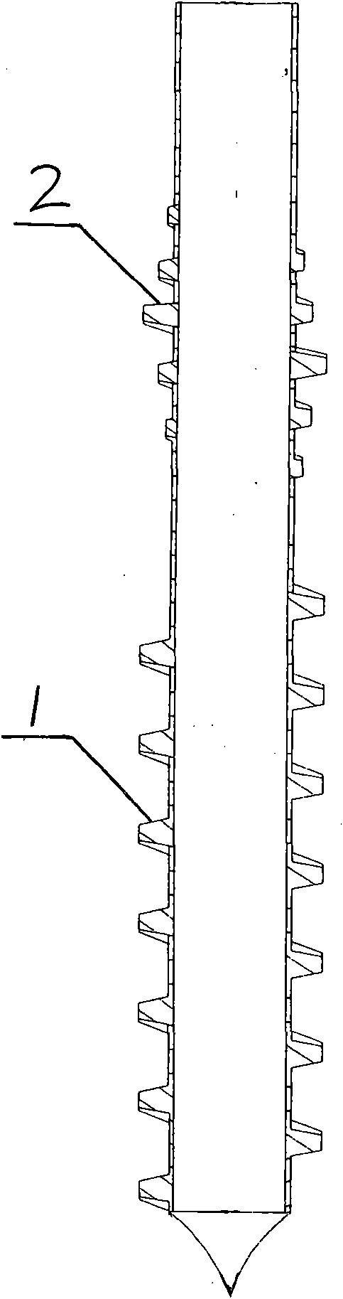
[0032] exist figure 1 , figure 2 In the shown structure, the lower part of the screw pile pile-forming drilling tool designed by the present invention is provided with a forward (clockwise) drilling thread 1 with equal cross-section and equal pitch, and a reverse (counterclockwise) screw thread can be installed and disassembled on the upper part of the drilling tool. ) equal-pitch sweeping thread 2, and the sweeping thread 2 is fixed on the drill pipe with a fixture according to the design requirements of the straight rod section of the pile body before construction.

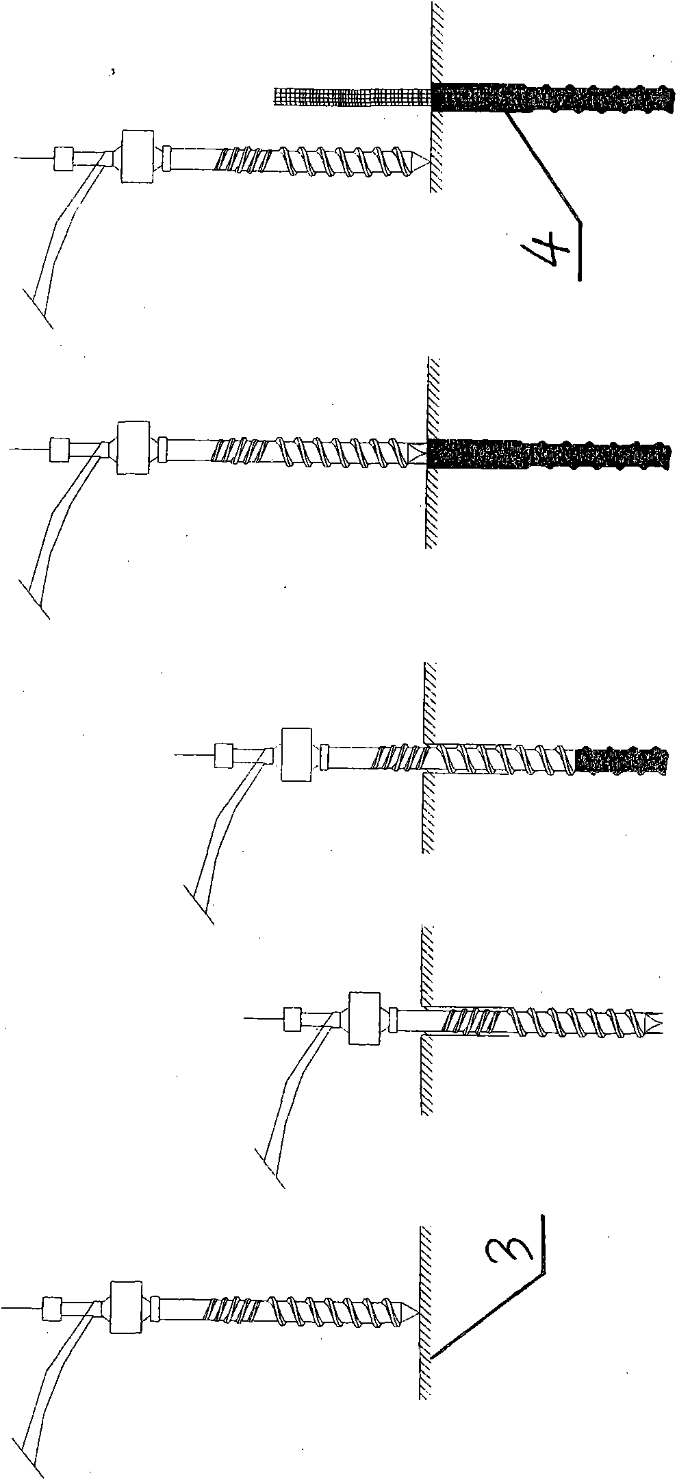
[0033] Such as image 3 Shown, the screw pile pile-forming method provided by the present invention comprises the following steps:

[0034] Step 1: Use special equipment for screw piles to match the above drill pipes to align the piles;

[0035] Step 2: The pile-forming drilling tool adopts forward synchronous technology within the pile length range to rotate the drilling thread 1 of the lower part of the dr...


PUM


Abstract

The invention relates to a pile-forming drilling tool for a screw pile and a pile-forming construction method thereof, wherein forward drilling threads are arranged at the lower part of the pile-forming drilling tool, and backward sweeping threads are detachably arranged on the upper part thereof. The pile-forming construction method comprises the following steps: adopting special screw pile equipment to be assorted with the drilling tool to align with a pile position; utilizing the drilling tool to drill downwards so as to form threaded soil holes to reach the design depth of the pile, and meanwhile utilizing the sweeping threads at the upper part of the drilling tool to extrude and sweep the soil threads to form straight holes which reach the design depth of a straight lever section; lifting up the drilling tool in a rotating mode, and simultaneously concreting to form the thread section and the straight lever section of the pile; and after concreting is completed, placing a reinforcing cage to form the reinforced concrete screw pile. The drilling tool provided by the invention can effectively eliminate part of a threaded soil mass to form the straight holes by adopting forward threads and backward threads, thus achieving the effect of forming screw pile holes by boring at a time and realizing hole-forming and pile-forming of the screw pile at a time; and the pile-forming construction method has simple working procedures, faster speed, reduced construction resistance and no need of taking soil.

Description

technical field [0001] The invention belongs to the field of construction, and relates to a pile-forming drilling tool and a pile-forming method thereof, in particular to a screw pile-forming pile-forming drill tool and a pile-forming method thereof. Background technique [0002] The screw pile is a new type of pile in civil engineering. It is a "cylindrical upper part and a screw lower part" combined pile. During the construction process, the pile machine drilling tool is used to rotate and squeeze the soil and pump the concrete to form a pile. , no noise, no vibration, applying the principle of "screws are stronger than nails" in common sense to the construction of piles and piles, it has high strength, short construction period, high efficiency, small settlement, earthquake resistance, no soil extraction, no slurry discharge , No pollution, construction and pile quality are not affected by groundwater, wide application range, adaptable to various soil layers and other adv...

Claims


Application Information

Patent Timeline
Patent Type & Authority Applications(China)
IPC IPC(8): E02D5/36E02D5/56E21B10/44E21B17/22
Inventor 彭桂皎彭樱谭燕姬
Owner 彭桂皎
Why Eureka
Try Eureka