Eureka AIR delivers breakthrough ideas for toughest innovation challenges, trusted by R&D personnel around the world.

Rotary lifting device

A lifting device and a rotating technology, applied in the direction of cranes, etc., can solve the problems of single lifting point unable to turn, reduce lifting traction, etc., achieve the effect of easy control of traction, reduce lifting traction, and improve versatility

Inactive Publication Date: 2010-11-24
XUZHOU POWER SUPPLY OF JIANGSU ELECTRIC POWER
View PDF6 Cites 4 Cited by
  • Summary
  • Abstract
  • Description
  • Claims
  • Application Information

AI Technical Summary

Problems solved by technology

[0005] The beneficial effects of the present invention are: (1) the rotatable design is adopted to solve the problem that the single lifting point cannot be turned; (2) the moving pulley block is adopted to greatly reduce the lifting traction force; (3) the static pulley is adopted to change the lifting traction force direction, easy to control the traction force; (4) The pillars are fixed with a variety of size fits, which are suitable for the isolation switch foundation of each voltage level and improve the versatility of the device

Method used


Image

  • Rotary lifting device
  • Rotary lifting device
  • Rotary lifting device

Examples


Embodiment Construction

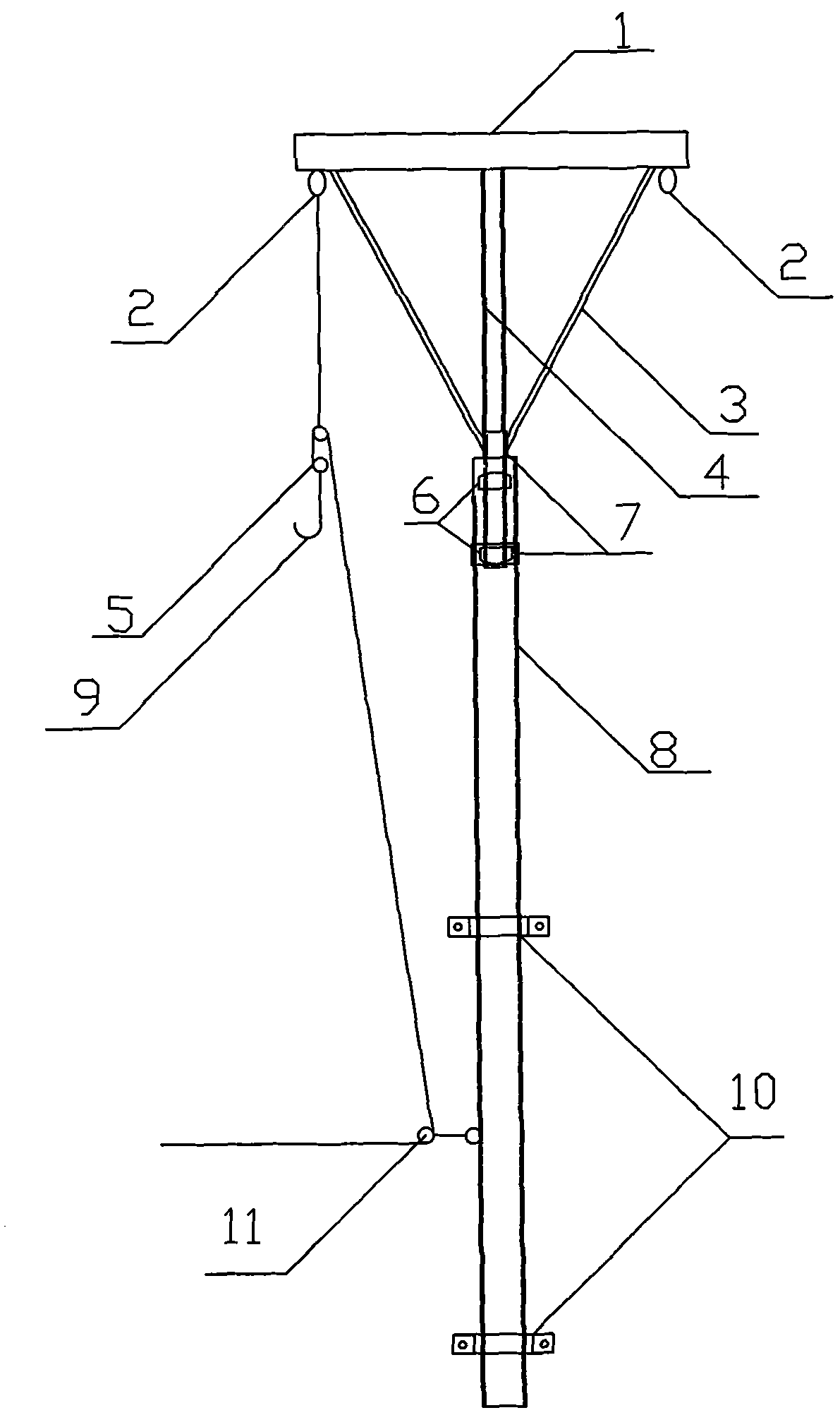
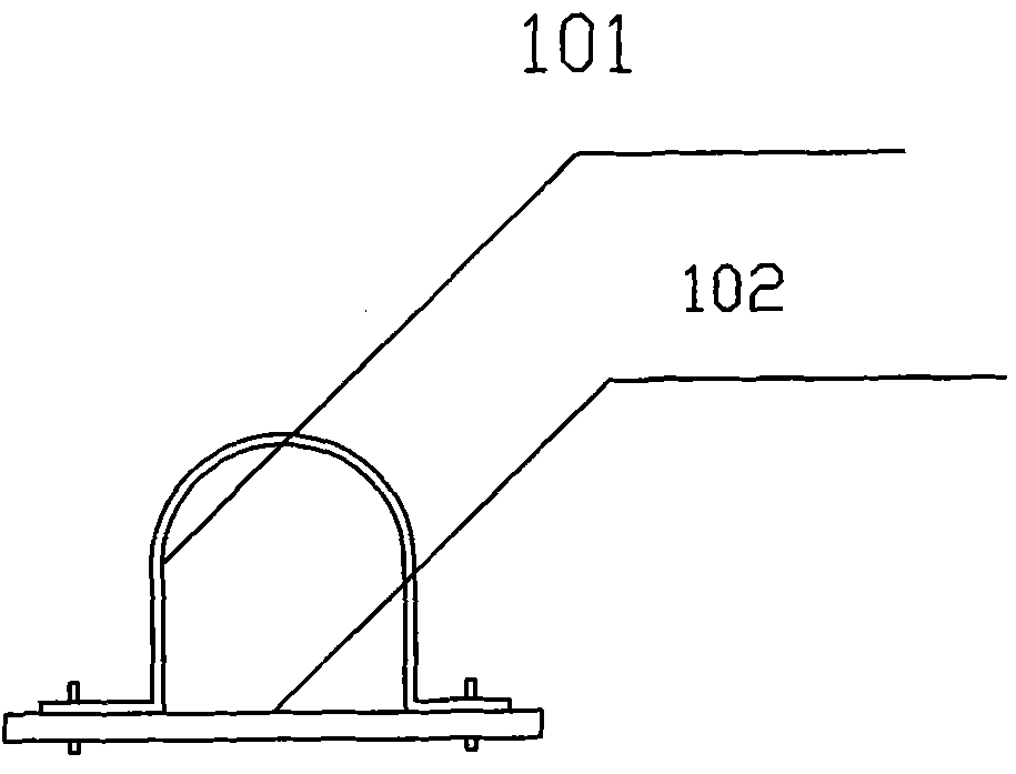
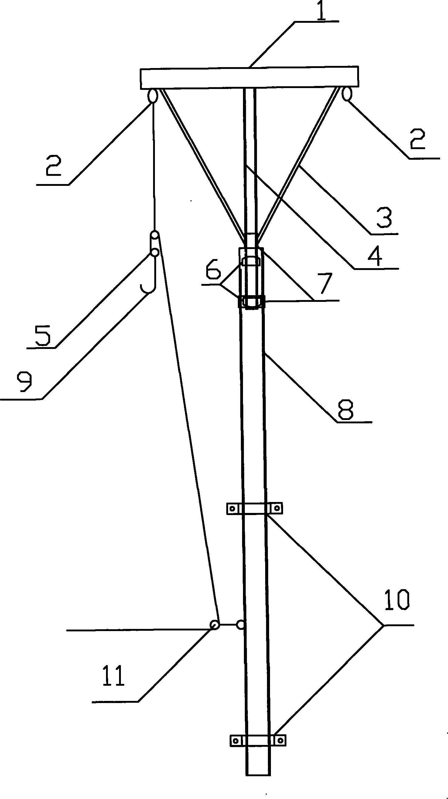
[0010] Such as figure 1 As shown, the rotary hoisting device has a pillar, and the pillar is composed of an upper support rod 4 and a lower support rod 8; a circular groove is arranged on the upper end of the lower support rod 8, and a bearing 6 is housed in the circular groove, and the upper support rod 4 passes through the bearing 6 and the The lower support rod 8 is connected; in the present embodiment, the upper support rod 4 and the lower support rod 8 adopt steel pipes, and the bearing 6 is fixed by embedding the inner wall of the lower support rod 8 to ensure that the upper and lower support rods are concentric. In order to increase the strength of the joint between the upper support bar 4 and the lower support bar 8 , a clamping rib 7 is installed at the joint of the upper support bar 4 and the lower support bar 8 . The upper end of the upper support bar 4 is equipped with a lifting device, which is composed of a static pulley block 11 fixed on the lower support bar 8 ...


PUM


Abstract

The invention discloses a rotary lifting device and relates to the technical field of the lifting device. The device comprises a pillar, a fixing device used for fixing the pillar and a hoisting device arranged on the pillar, wherein the pillar consists of an upper support bar and a lower support bar; the upper support bar is connected with the lower support bar, the upper support bar can rotate in the lower support bar; the hoisting device comprises a stationary pulley block fixed on the lower support bar and a cross arm fixed on the upper end of the upper support bar; and lugs are fixed on both ends of the lower end face of the cross arm, and a movable pulley block is suspended on the lugs. The beneficial effects of the invention are as follows: the problem that the single point lifting device can not change direction; the lifting traction force is greatly reduced; and the device is convenient to control and has wide application range.

Description

technical field [0001] The invention relates to the technical field of hoisting devices, in particular to a rotary hoisting hoisting device. Background technique [0002] With the increase of technical upgrading projects, it has become an important task for us to replace the equipment, especially the isolating switch, in the substations that have been put into operation. It is often impossible to use mechanical equipment such as cranes during the replacement of isolating switches. How to hoist the new isolating switch to the foundation in a limited space and save time and effort has become the key to this work. The traditional simple lifting device adopts the method of fixing the lifting point on the frame and lifting it manually. During the construction process, there are disadvantages such as the lifting point cannot be rotated, the traction force required for human lifting is large, and the excessive swing of the traction rope is too long, causing safety hazards and other...

Claims


Application Information

Patent Timeline
Patent Type & Authority Applications(China)
IPC IPC(8): B66C23/02B66C23/16
Inventor 孙爱民宋庆元郑广轩丁然
Owner XUZHOU POWER SUPPLY OF JIANGSU ELECTRIC POWER
Why Eureka
Eureka Blog
Learn More