Optical network system, optical line terminal, optical network unit and optical distribution network device

A technology for optical line terminals and optical network units, applied in optical network units and optical distribution network devices, hybrid passive optical network systems, and optical line terminals, can solve the problem of large bandwidth, limited number of code multiplexing, and restricted system access Problems such as the number of users, to achieve the effect of overcoming security vulnerability, large access user capacity, and high network security

Inactive Publication Date: 2010-12-01
ZTE CORP +1
View PDF3 Cites 25 Cited by
  • Summary
  • Abstract
  • Description
  • Claims
  • Application Information

AI Technical Summary

Problems solved by technology

[0012] However, the optical code division multiple access passive optical network (OCDMA-PON) system also has its inherent disadvantages: the number of code multiplexing is limited, which limits the number of users accessing the system; as the number of multiplexing increases, the number of users The crosstalk is gradually increasing, which affects the number of access users of the system to a certain extent; OCDMA is a spread spectrum technology that requires a large bandwidth. Due to the inherent defects of BER caused by interference between users, it affects the access users of the system quantity

Method used


Image

  • Optical network system, optical line terminal, optical network unit and optical distribution network device
  • Optical network system, optical line terminal, optical network unit and optical distribution network device
  • Optical network system, optical line terminal, optical network unit and optical distribution network device

Examples


Embodiment Construction

[0068] In order to make the object, technical solution and advantages of the present invention clearer, the present invention will be described in detail below with reference to the accompanying drawings and specific embodiments.

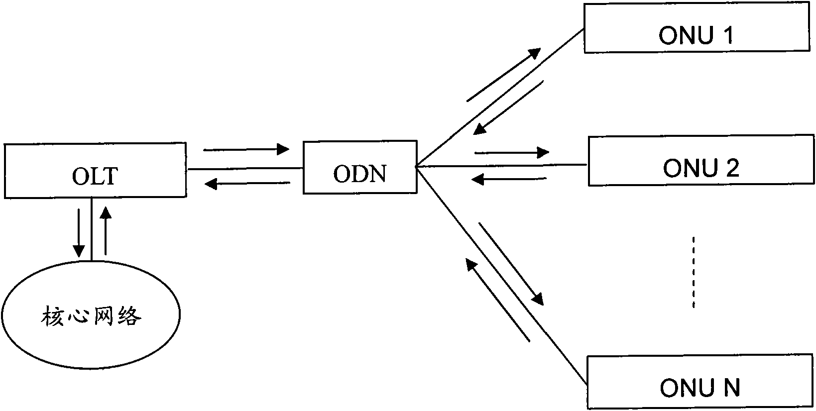
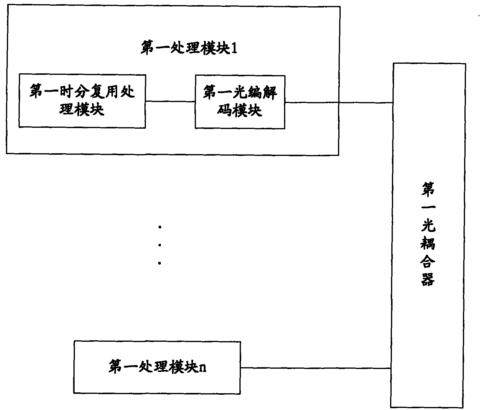
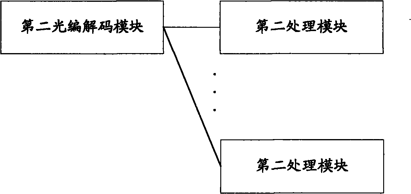
[0069] The invention provides a hybrid passive optical network system, which is used to realize the hybrid of time division multiplexing passive optical network and optical code division multiple access passive optical network, including: an optical line terminal, used to time-division multiplex The downlink signal modulation and coding of different channels use different codes for time-division multiplexing downlink signals, and the encoded downlink signals of each channel are combined into one and then output; and the uplink signal is received, and the received uplink signal is decoded and output ; The optical distribution network is used to receive the downlink signal output by the optical line terminal, divide the received downlink signal into mu...


PUM


Abstract

The invention provides an optical network system, an optical line terminal, an optical network unit and an optical distribution network device. The optical network system comprises the optical line terminal, an optical distribution network and the optical network unit, wherein the optical line terminal is used for modulating and codling at least one path of descending signal subjected to the time-division multiple, outputting the coded signals after combining the coded signals into one path, receiving ascending signals and outputting the ascending signals after decoding the received ascending signals; the optical distribution network is used for outputting the received ascending signals after dividing the received ascending signals into multiple paths and outputting the received ascending signals to the optical line terminal after converging the received ascending signals into one path; the optical network unit is used for receiving the ascending signals output by the optical distribution network, outputting the received descending signals after decoding the received descending signals, coding a path of time-division multiplexing ascending modulation signals and outputting the coded signals to the optical distribution network; and the optical distribution network can decode the descending signals and code the ascending signals. The invention can realize a mixed passive optical network system based on time-division multiplexing technology and optical code division multiple access technology.

Description

technical field [0001] The invention relates to the technical field of optical fiber communication, in particular to a hybrid passive optical network system, an optical line terminal, an optical network unit and an optical distribution network device. Background technique [0002] In current data communication, the access network becomes the infrastructure of the communication network since it is the transport entity of the Service Interface (SNI) and the associated User Network Interface (UNI). Because of this feature, the access network should adopt a fair, flexible and secure multiple address technology. Passive Optical Network (PON, Passive Optical Network) has become a popular technology in optical access network because of its wide frequency bandwidth, large capacity, convenient expansion, and suitability for high-speed data transmission. It is also the most widely used technology in optical access network technology. [0003] Typical passive optical networks, such as...

Claims


Application Information

Patent Timeline
Patent Type & Authority Applications(China)
IPC IPC(8): H04J14/02H04J14/08H04B10/20H04Q11/00H04B10/272
CPCH04B10/272H04Q2011/0064H04Q11/0067H04J14/005
Inventor 陈彪成亮王大伟朱松林耿丹
Owner ZTE CORP
Why Eureka
Try Eureka