
Pencil sharpener for flat pencil point

A pencil sharpener, flat-shaped technology, applied in sharpening devices, printing, office supplies, etc., can solve the problems of wasting pencils, inconvenience, and prone to accidents.

Inactive Publication Date: 2011-02-16
徐国元
View PDF4 Cites 17 Cited by
  • Summary
  • Abstract
  • Description
  • Claims
  • Application Information

AI Technical Summary

Problems solved by technology

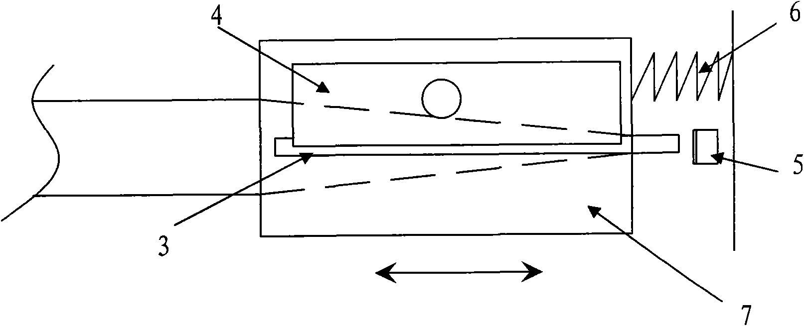
[0003] At present, its structure of generally used pencil sharpener is: as Figure 4 As shown, a knife seat 7 with a tapered insertion hole is provided with a strip chip hole 3 on one side of the tapered insertion hole, and a blade 4 is fixed on one side of the strip chip hole, in order to make the pencil be drawn Sharpened, the end of the tapered insertion hole is a circular hole with a diameter slightly larger than the diameter of the pen core, but the tapered point formed by the extension of the tapered insertion hole is located in the knife seat, and the knife set corresponding to the tapered point There is a blade on the seat, usually the length of the blade is slightly longer than the tip of the cone; when in use, insert the pencil into the cone-shaped insertion hole, and then rotate the pencil against the edge of the blade until the barrel and refill are cut into a conical shape; And in aspects such as design, drafting, drawing, painting card, engineering construction, the nib of this pencil will be cut into flat shape (square or rectangle) when using usually, so existing pencil sharpener is then incompetent, can only use pocket knife or blades, etc., are inconvenient, waste pencils, and are prone to accidents

Method used


Image

  • Pencil sharpener for flat pencil point
  • Pencil sharpener for flat pencil point
  • Pencil sharpener for flat pencil point

Examples


Embodiment Construction

[0017] The present invention will be further described below in conjunction with the accompanying drawings and embodiments.

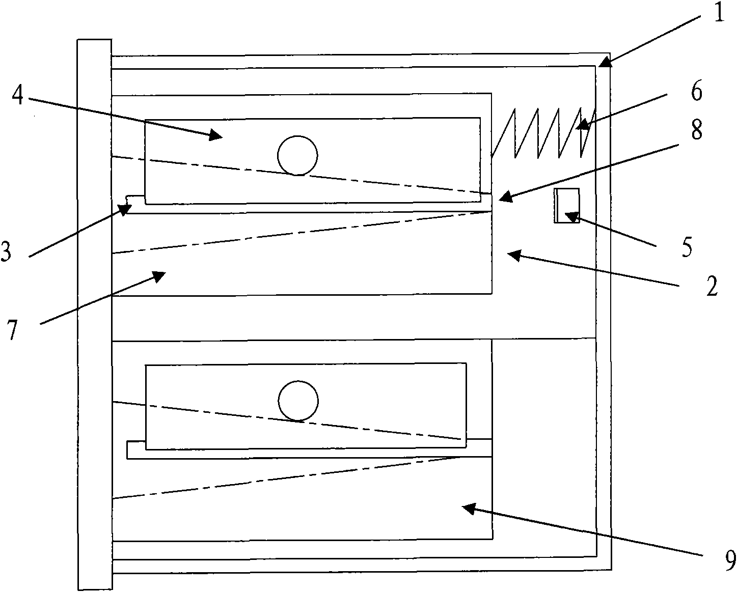
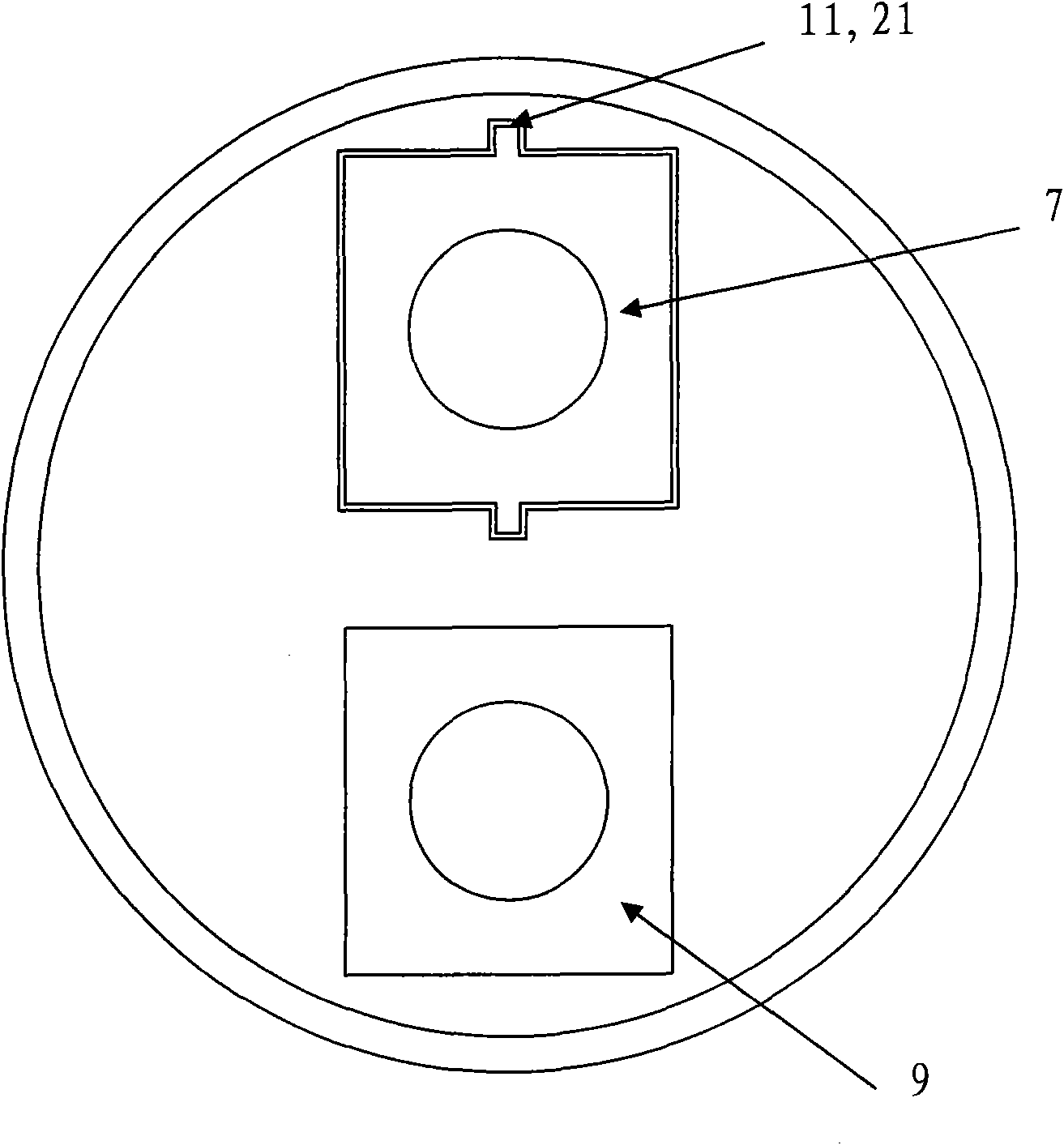
[0018] Such as Figure 1 to Figure 3 Shown, the flat nib pencil sharpener of the present invention comprises:

[0019] A cylindrical housing 1, the housing can be square or cylindrical; guide rails or guide grooves 11 are arranged axially on the inner wall of the housing;

[0020] A pencil sharpener, comprising: a knife seat 7 with a tapered insertion hole, a chip outlet 3 is provided on one side of the tapered insertion hole, and a knife seat on the side of the chip outlet is fixed with a Cutting blade 4; at the bottom of the tapered insertion hole, a pencil lead extension hole 8 equivalent to the diameter of the pencil lead is provided; on both sides of the knife seat, there are guide grooves matching the housing guide rail or guide groove Or guide rail 21, described pen sharpener knife is located in cylindrical housing and can slide along guide rai...


PUM


Abstract

The invention discloses a pencil sharpener for a flat pencil point, which solves the problems of troublesome sharpening and the like in the prior art. The pencil sharpener comprises a cylindrical shell, a pencil sharpener, a flat pencil point knife edge and a return spring, wherein a guide rail or a guide slot is axially arranged on the inner wall of the shell; both sides of the knife seat are provided with a guide slot or a guide rail matched with the guide rail or the guide slot of the shell, and the penholder sharpener is arranged in the cylindrical shell and can slide along the guide railor the guide slot; the flat pencil point knife edge is arranged on the bottom of the shell in the position corresponding to a pencil lead stretching hole; and the return spring is arranged between the inner bottom of the shell and the bottom of the penholder sharpener. The penholder part of a pencil can be firstly sharpened into conical by using the structure, the pencil lead part stretches out of the knife seat, the knife seat is moved backward to ensure that the pencil lead is inserted into the flat pencil point knife edge, the flat pencil point knife edge cuts the pencil lead, and the purpose of cutting the pencil point into flat (square or rectangular) is achieved.

Description

technical field [0001] The invention relates to a pencil sharpener, in particular to a flat-tip pencil sharpener. Background technique [0002] A pencil is usually composed of a wooden barrel and a pen core provided in the barrel, and the barrel cross section is usually round or multi-edged. [0003] At present, its structure of generally used pencil sharpener is: as Figure 4 As shown, a knife seat 7 with a tapered insertion hole is provided with a strip chip hole 3 on one side of the tapered insertion hole, and a blade 4 is fixed on one side of the strip chip hole, in order to make the pencil be drawn Sharpened, the end of the tapered insertion hole is a circular hole with a diameter slightly larger than the diameter of the pen core, but the tapered point formed by the extension of the tapered insertion hole is located in the knife seat, and the knife set corresponding to the tapered point There is a blade on the seat, usually the length of the blade is slightly longer th...

Claims


Application Information

Patent Timeline
IPC IPC(8): B43L23/06B43L23/08
Inventor 徐国元
Owner 徐国元
Learn More