Supercharge Your Innovation With Domain-Expert AI Agents!

Ultrasonic flaw detection method and device

An ultrasonic, rolling direction technology, applied in measuring devices, using sonic/ultrasonic/infrasonic waves to analyze solids, and using sonic/ultrasonic/infrasonic waves for material analysis, etc., can solve problems such as difficult calculation efficiency and calculation accuracy

Active Publication Date: 2011-04-13
NIPPON STEEL CORP
View PDF1 Cites 7 Cited by
  • Summary
  • Abstract
  • Description
  • Claims
  • Application Information

AI Technical Summary

Problems solved by technology

Therefore, it is difficult to achieve a balance between computational efficiency and computational accuracy

Method used


Image

  • Ultrasonic flaw detection method and device
  • Ultrasonic flaw detection method and device
  • Ultrasonic flaw detection method and device

Examples


Embodiment

[0071] Hereinafter, the present invention will be described in more detail by showing examples.

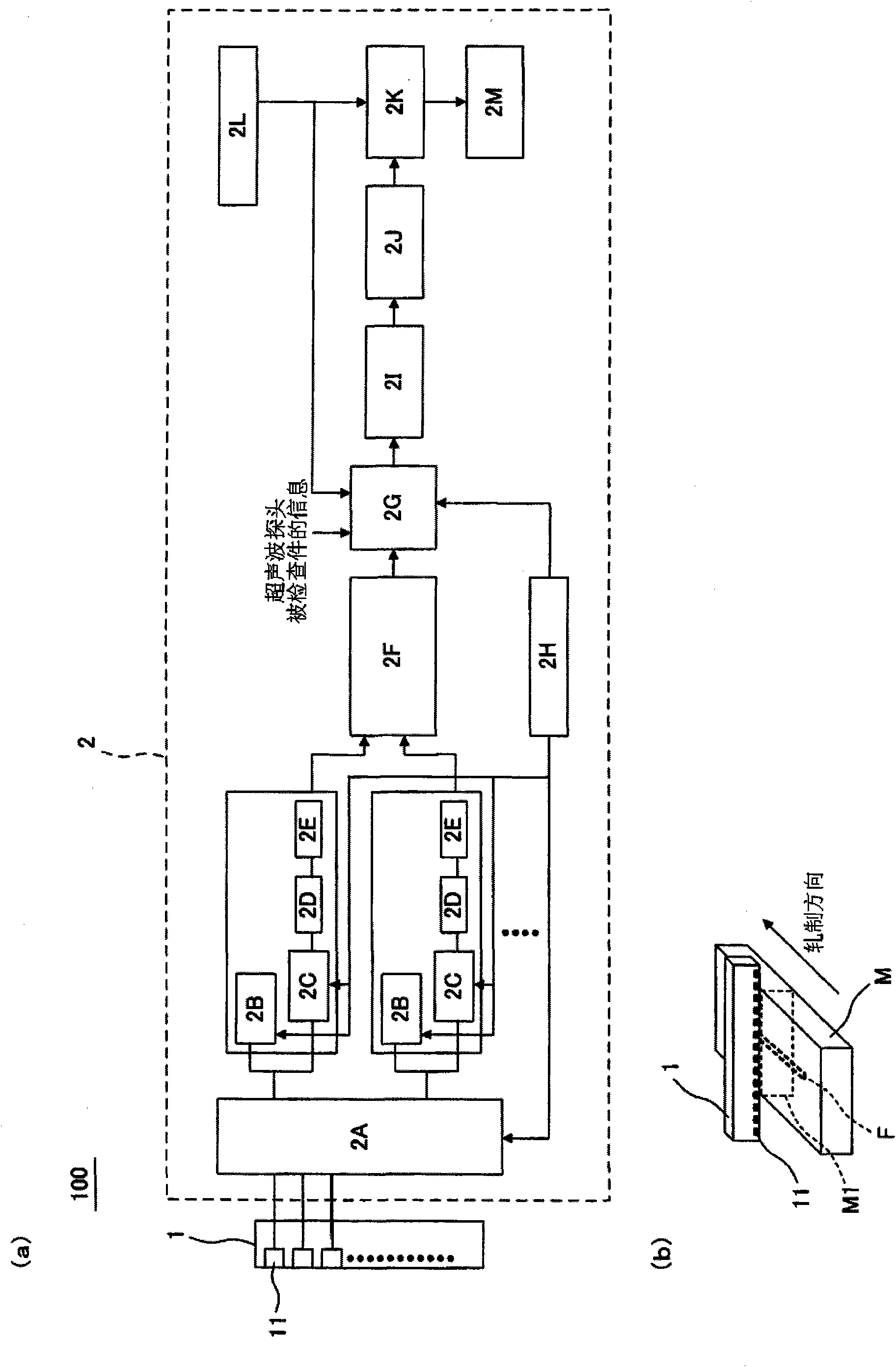
[0072] The flat-bottomed groove (inclined 10° relative to the horizontal direction of the plate, 3.6mm in width, and 20mm in length) set in the plate as a defect is used in figure 2 A flaw detection test was carried out with the ultrasonic flaw detector of the present invention having a schematic configuration shown in . As a linear array ultrasonic probe, a flaw detection frequency of 5 MHz, an array pitch of 0.5 mm of transducers, 64 transducers, and a length of 6 mm of transducers in a direction perpendicular to the array direction were used. The synthetic aperture image is generated by moving the ultrasonic probe relative to the inspection object by 1 mm at a time.

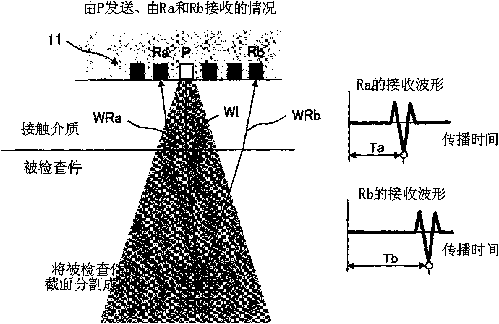
[0073] Figure 5 (a) is an example of a synthetic aperture image obtained in this example. The synthetic aperture image is obtained by transmitting ultrasonic waves with any one transducer, receiving ultrasoni...


PUM


Abstract

An ultrasonic flaw detection device (100) is provided with a one-dimensional array ultrasonic probe (10), in which a plurality of vibrators (11) are arranged in a direction perpendicular to the rolling direction of a material to be inspected (M), and a signal processing means (2). The signal processing means executes the following (1) to (6). (1) The signal processing means generates an aperture composite image of a flaw detection signal for each cross section of the material to be inspected. (2) The signal processing means generates the distribution of the maximum value of the flaw detection signals in the direction in which the vibrators are arranged. (3) The signal processing means calculates the width of a flaw in each cross section according to the distribution of the maximum value. (4) The signal processing means generates the distribution of the maximum value of flaw detection signals in the rolling direction from the distribution of the maximum value in a plurality of the cross sections of the material to be inspected. (5) The signal processing means calculates the length of the flaws according to the distribution of the maximum value of the flaw detection signals in the rolling direction. (6) The signal processing means calculates the areas of the flaws according to the length of the flaws calculated and the width of the flaw of each cross section calculated.

Description

technical field [0001] The present invention relates to an ultrasonic flaw detection method and device capable of measuring the area of ​​a defect extending along the rolling direction of an inspected object with high precision and simply. Background technique [0002] In order to ensure the quality of rolled metal products (including semi-finished products) such as iron and steel products, ultrasonic flaw detection is used to detect defects existing in the product and determine whether it is qualified or not. The criteria for judging pass / fail are defined by, for example, the size of the defect to be detected. For example, API Standard 5CT, which is one of the relevant standards for steel pipes for oil wells, stipulates that in the case of a defect with no opening on the surface (not exposed to the inner and outer surfaces of the steel pipe) detected in the steel pipe, the area of ​​the defect shall not exceed 260mm 2 (API Specification 5CT / ISO 11960). Thus, the area of ​...

Claims


Application Information

Patent Timeline
Patent Type & Authority Applications(China)
IPC IPC(8): G01N29/44G01N29/04
CPCG01N2291/2632G01N29/265G01N29/069G01N29/262G01N2291/106
Inventor 上田佳央山野正树池田正美
Owner NIPPON STEEL CORP
Features
  • R&D
  • Intellectual Property
  • Life Sciences
  • Materials
  • Tech Scout
  • Unparalleled Data Quality
  • Higher Quality Content
  • 60% Fewer Hallucinations
Learn More