Driver awareness degree judgment device, method, and program

A technology for judging device and attention, which is applied to the safety device, optical observation device, transportation and packaging of the power device control mechanism, etc., can solve the problem of not being able to measure the attention level of the peripheral visual field area.

Inactive Publication Date: 2011-05-04
PANASONIC CORP
View PDF5 Cites 44 Cited by
  • Summary
  • Abstract
  • Description
  • Claims
  • Application Information

AI Technical Summary

Problems solved by technology

Therefore, the measured driving attention level is limited to the driver's central vision area, and the attention level for the peripheral vision area cannot be measured.

Method used


Image

  • Driver awareness degree judgment device, method, and program
  • Driver awareness degree judgment device, method, and program
  • Driver awareness degree judgment device, method, and program

Examples


Embodiment approach 1

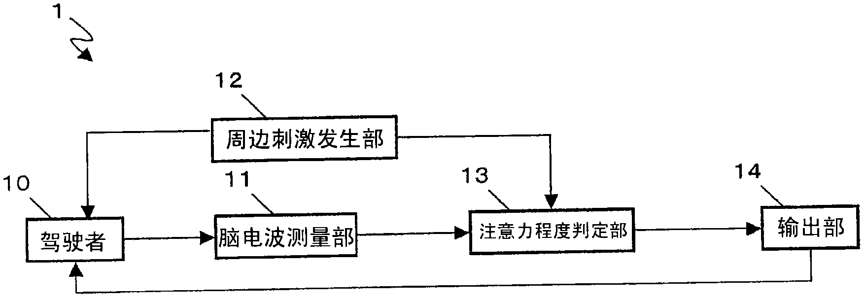
[0063] figure 2 It is a block configuration diagram showing the driving attention level determination device 1 of the present embodiment.

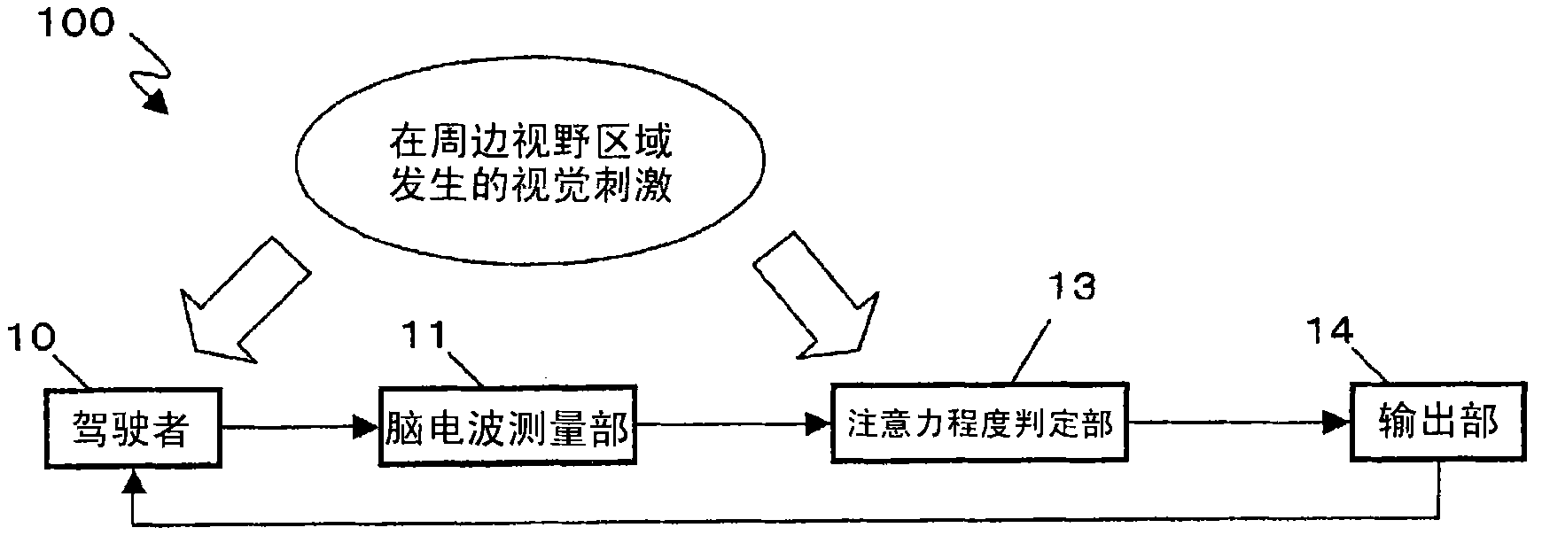
[0064] The driving attention level determination device 1 is a device that determines the level of attention to driving using the electroencephalogram signal of the driver 10 and provides assistance based on the determination result. For example, brainwaves are used to determine the degree of attention to events that may occur in the driver's peripheral field of vision, such as sudden vehicle intrusion or pedestrian rushing out, and the driver's attention can be drawn based on the determination results.

[0065] The driving attention level determination device 1 includes an electroencephalogram measurement unit 11 , a peripheral stimulus generation unit 12 , an attention level determination unit 13 , and an output unit 14 . The block for the driver 10 is shown for ease of illustration.

[0066] The outline of the hardware configuration ...

Embodiment approach 2

[0128] The imaging unit for imaging the front of the host vehicle is provided in the driving attention level determination device of the present embodiment. This device for determining the degree of attention to driving detects the occurrence of visual stimuli that serve as a starting point for analyzing the event-related potentials of brain waves based on images captured by the imaging unit, and distinguishes the central visual field area and the Peripheral vision area. And determine the degree of attention in the peripheral vision area.

[0129] Thereby, it is possible to use the natural visual stimuli that occur in front of the driver during driving from the front captured image without intentionally sending out visual stimuli from the driving attention level judging device as in Embodiment 1 to determine whether the peripheral vision is affected. area of ​​attention.

[0130] Figure 13 A block configuration diagram showing the driving attention level determination devi...

Embodiment approach 3

[0158] In Embodiment 2, the stimulus generation area is determined on the premise that the driver basically looks at the center of the front during driving. However, when visual stimuli occur, the driver's line of sight is not always directed toward the center of the front, so the peripheral vision area often changes.

[0159] Therefore, in the present embodiment, a line-of-sight measuring unit that measures the line-of-sight of the driver is provided in the driving attention level determination device. The driving attention level determination device determines a visual stimulation occurrence area based on the position of the driver's gaze point.

[0160] Figure 18 A block configuration diagram showing the driving attention level determination device 3 of the present embodiment. The driving attention degree judging device 3 is relative to the driving attention degree judging device 2 ( Figure 13 ) is constructed by adding a line of sight measurement unit 18.

[0161] ...


PUM


Abstract

The invention provides a driver awareness degree judgment device, a method, and a program. Even when a driver does not give an eyeshot to a peripheral object, it is possible to determine the driver's awareness degree in the driver's peripheral view-field region and support safe driving in accordance with the judgment result. Provided is a driver awareness degree judgment device including: a brainwave measurement unit which measures a driver's brain wave signal; an awareness degree judgment unit which determines the driver's awareness degree relating to the driver's peripheral view-field region in accordance with the measured brain wave signal starting at the moment when a visual stimulus is generated in the driver's peripheral view field region; and an output unit which outputs a signal based on the judgment result so as to promote driver's awareness.

Description

technical field [0001] The present invention relates to the technology of judging the driver's state by using brain waves to assist safe driving. Background technique [0002] In recent years, in an accident prevention device related to automobile driving, a method of judging the driver's state and assisting driving based on the judgment result has been studied. Perception of dangerous objects is one of the driver's visual cognition functions required for safe driving. The detection of dangerous objects refers to the detection of dangerous movements of surrounding vehicles or pedestrians through peripheral vision. If the detection function is reduced, it will lead to collision accidents or run-out accidents. [0003] The "peripheral field of view" generally refers to an area of ​​130 degrees up and down and 180 degrees left and right outside the range of about 20 degrees around the line of sight (central field of view). We know that although it is difficult to recognize th...

Claims


Application Information

Patent Timeline
Patent Type & Authority Applications(China)
IPC IPC(8): G08G1/16A61B3/113A61B5/0476A61B5/0484A61B5/18B60R1/00B60R11/02B60R11/04B60W40/08
CPCA61B3/113A61B5/18A61B2503/22B60K28/066A61B5/163A61B5/378A61B5/369G06V40/19G06V20/597
Inventor 中田透森川幸治
Owner PANASONIC CORP
Why Eureka
Try Eureka