Double-flow biomass gasified gas purification device

A purification device and biomass technology, applied in the manufacture of combustible gas, bulk chemical production, petroleum industry, etc., can solve the problems of unscientific structure design of gasifier, low reaction temperature of gasifier, and more tar and waste water. , to achieve the effect of reducing tar content, good gas quality and less environmental pollution

Inactive Publication Date: 2011-06-01
林口信安建材板业有限公司
View PDF4 Cites 22 Cited by
  • Summary
  • Abstract
  • Description
  • Claims
  • Application Information

AI Technical Summary

Problems solved by technology

[0003] In order to solve the problems of unscientific structural design of the existing gasification furnace, resulting in low reaction temperature of the gasification furnace, high generation of tar and waste water, low gas production efficiency, many impurities in the output gas, and low calorific value, the present invention provides A double-flow biomass gasification gas purification device, the specific technical solution to solve the above problems is as follows:

Method used


Image

  • Double-flow biomass gasified gas purification device
  • Double-flow biomass gasified gas purification device
  • Double-flow biomass gasified gas purification device

Examples


specific Embodiment approach 1

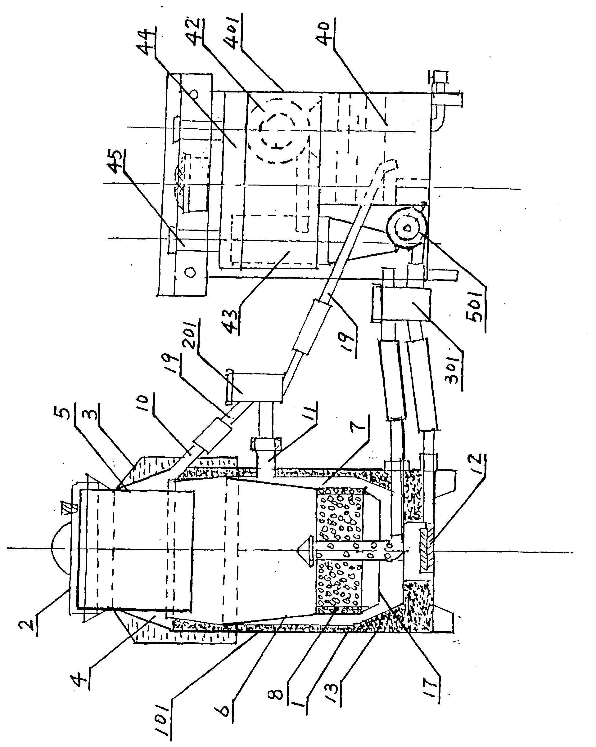
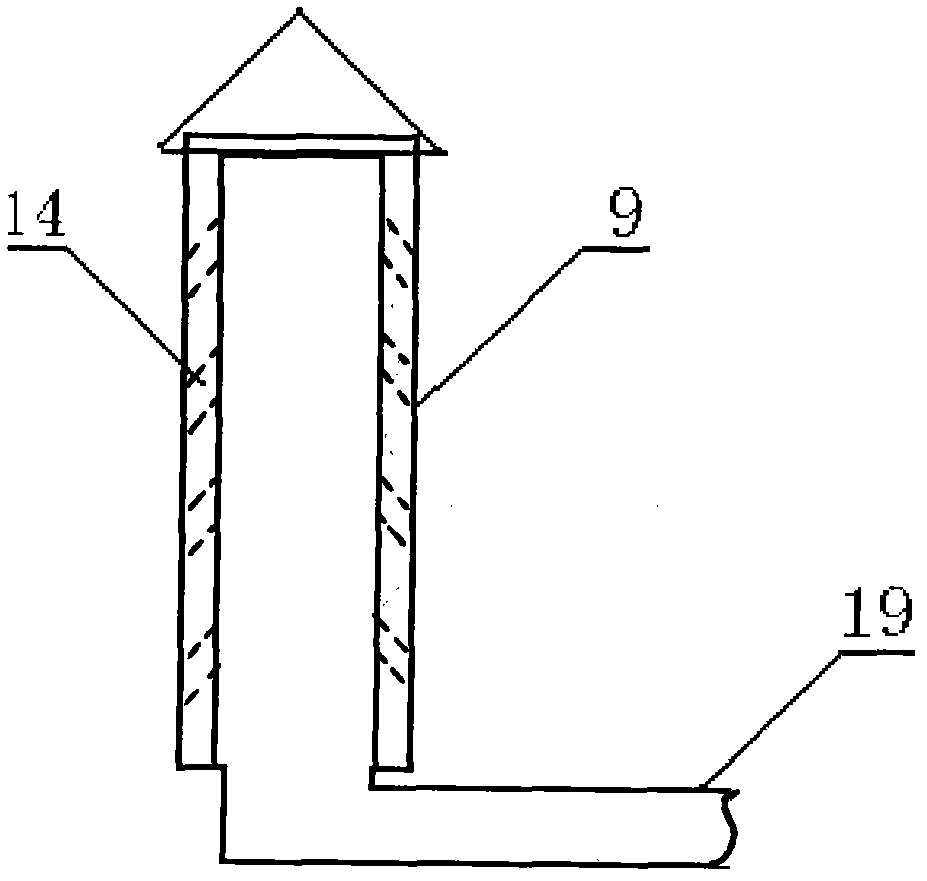
[0010] Specific implementation mode one: combine figure 1 , figure 2 , image 3 The present embodiment will be described. This embodiment consists of a gasifier 101, a gas flow control valve 201, a vortex oxygen-supporting control valve 301, a gas purifier 401, and a fan 501. The gasifier 101 consists of a furnace body 1, a sealing cover 2, a condenser 3, and an upper ring Composed of gas condensation chamber 4, feeding cylinder 5, dry distillation cracking cylinder 6, lower annular gas channel 7, catalytic cracker 8, vortex air distributor 9, infrared electric starter 12 and insulation layer 13, condenser 3 is located in the furnace body 1. The upper part, the upper annular gas condensation chamber 4 is arranged between the inner wall of the condenser 3 and the outer wall of the feeding cylinder 5, and the dry distillation cracking cylinder 6 is arranged below the feeding cylinder 5. The dry distillation cracking cylinder 6 is in an inverted trapezoidal shape. A catalytic...

specific Embodiment approach 2

[0011] Specific implementation mode two: combination figure 1 , Figure 4 The present embodiment will be described. The gas flow control valve 201 described in this embodiment is composed of an outer valve body 20, an inner valve body 21, an inner valve body rotary knob 22, a mesh cylinder 29 and a dry filter material 61, and the inner valve body 21 is provided with an upper gas inlet hole 23 and evacuation and the lower gas inlet 24, the outer valve body 20 is provided with an evacuation port 25, a lower gas interface 27, an upper gas interface 26 and a gas output interface 28, and the upper gas inlet 23 is connected with the evacuation and lower gas inlet. The centerlines of the circular ends of the adjacent ends of the hole 24 are on the same vertical line, the centerlines of the circular ends of the non-adjacent ends are on the 180-degree angle line of the vertical line, and the upper gas inlet hole 23 and the upper gas interface 26 are on the same vertical line. On the ...

specific Embodiment approach 3

[0013] Specific implementation mode three: combination figure 1 , Figure 5The present embodiment will be described. The vortex oxygen-assisted control valve 301 described in this embodiment is composed of an outer valve body 30 , an inner valve body 31 , an inner valve body rotary knob 32 and an oxygen-enriched integrated area 39 , and the outer valve body 30 is provided with a vortex air distributor interface 33 , gas purifier oxygen increasing interface 34, infrared electric starter air distribution interface 35 and fan interface 36, the inner valve body 31 is provided with eddy current air distribution device hole 37, infrared electric heating starter distribution air hole 38 and purifier oxygen increasing The hole 60, the vortex air distribution device hole 37 on the inner valve body 31, the infrared electric starter air distribution hole 38 and the purifier oxygenation hole 60 are oval, and the eddy current air distribution device hole 37 and the purification oxygenatio...


PUM


Abstract

The invention relates to a gasified gas purification device, in particular to a double-flow biomass gasified gas purification device, which solves the problems of low reaction temperature of a gasification furnace, abundant generated tar and wastewater, low gas-producing efficiency and abundant impurities and low heat value of output gas, resulted from unscientific structure of the gasification furnace. The gasified gas purification device comprises a gasification furnace, a gas flow control valve, a vortex flow oxidation-assisted control valve, a gas purifier and a fan. The gasified gas purification device provided by the invention has the advantages of increasing the reaction temperature of the furnace, wherein the temperature in oxidation, reduction and pyrolysis cylinders is between 1,300 and 1,600 DEG; increasing the gasification intensity; being capable of quickly separating moisture in biomass combustible gas so that gas quality is better; ensuring greatly reduced tar content in the combustible gas, less wastewater generated, high gas-producing efficiency and low environmental pollution due to the adoption of a mesh-type catalytic cracking device; and removing tar, moisture and ash in the gas through the gas purifier so that the heat value of the gas is improved. The gasified gas purification device is widely applied in industrial and civil fields.

Description

technical field [0001] The invention relates to a gasification furnace and a gas purification device. Specifically relates to a dual-flow biomass gasification fuel gas purification device. Background technique [0002] At present, the gasifiers used to convert biomass into biomass gas are mainly divided into two types, one type is fixed bed type, and the other type is fluidized bed type. The fixed bed gas furnace is divided into four types: upflow type, cross flow type, downflow type and open type according to the direction in which the biomass combustible gas flows in the gas furnace. The biomass raw material is divided into a drying layer, a thermal decomposition layer (distillation layer), a reduction layer and an oxidation layer from top to bottom in the fixed-bed gas furnace. There are intersecting phenomena between various levels. The current various types of biomass gasification furnaces are characterized according to the direction in which the biomass combustible ...

Claims


Application Information

Patent Timeline
Patent Type & Authority Applications(China)
IPC IPC(8): C10J3/60C10J3/20C10J3/22C10J3/84C10J3/72
CPCY02P20/52
Inventor 王强那瑾王旭
Owner 林口信安建材板业有限公司
Why Eureka
Try Eureka