Switch control device for front door of heavy engineering equipment
A technology of engineering equipment and switch control, applied in switches with brakes, application of locks, door/window fittings, etc. Safety accident, the effect of easy opening and closing of the front door
Inactive Publication Date: 2011-06-08
DOOSAN INFRACORE CO LTD
5 Cites 4 Cited by
AI-Extracted Technical Summary
Problems solved by technology
[0007] The present invention is proposed in order to solve the above problems, and is to provide a front door switch control device for heavy construction equipm...
Abstract
The invention relates to a switch control device for the front door of heavy engineering equipment. When a switch is installed on the front door of a cab of heavy engineering equipment, the door can be easily lifted when the door is opened via a flexible element at the lower end of the front door, and the fast falling speed of the door due to gravity can be controlled when the front door is closed.
Application Domain
Vehicle locksBuilding braking devices +2
Technology Topic
EngineeringMechanical engineering
Image
Examples
- Experimental program(1)
Example Embodiment
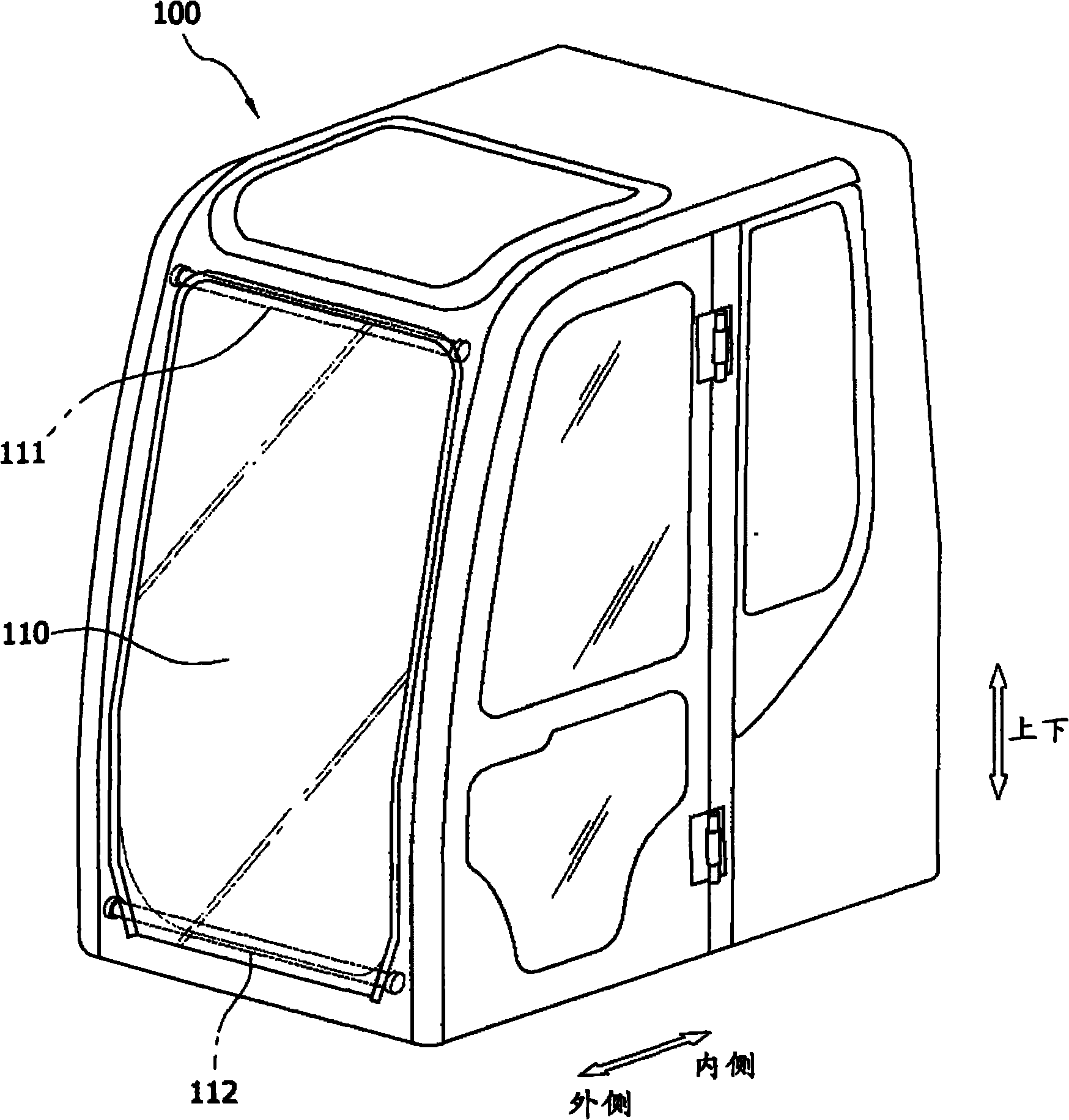
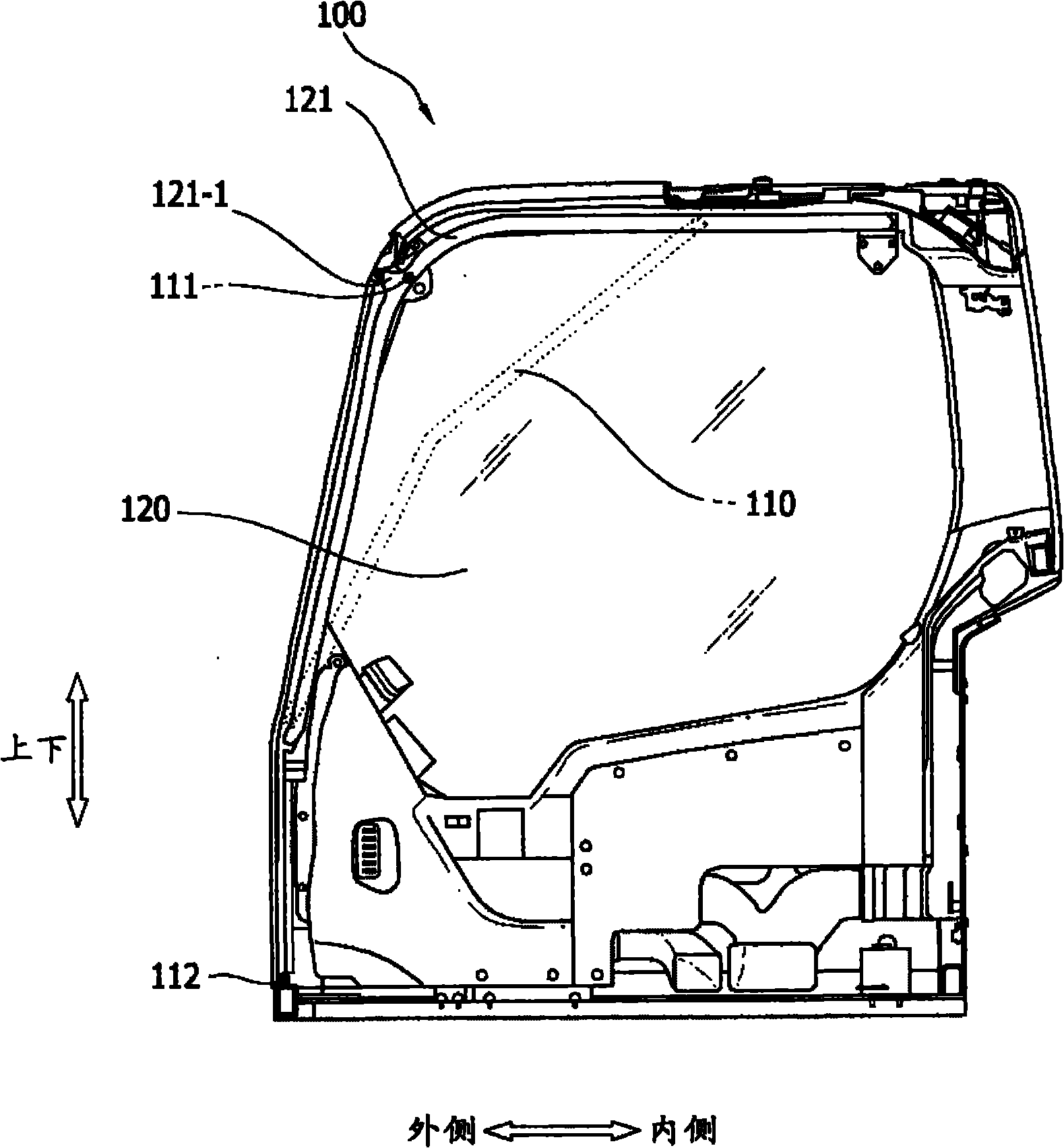
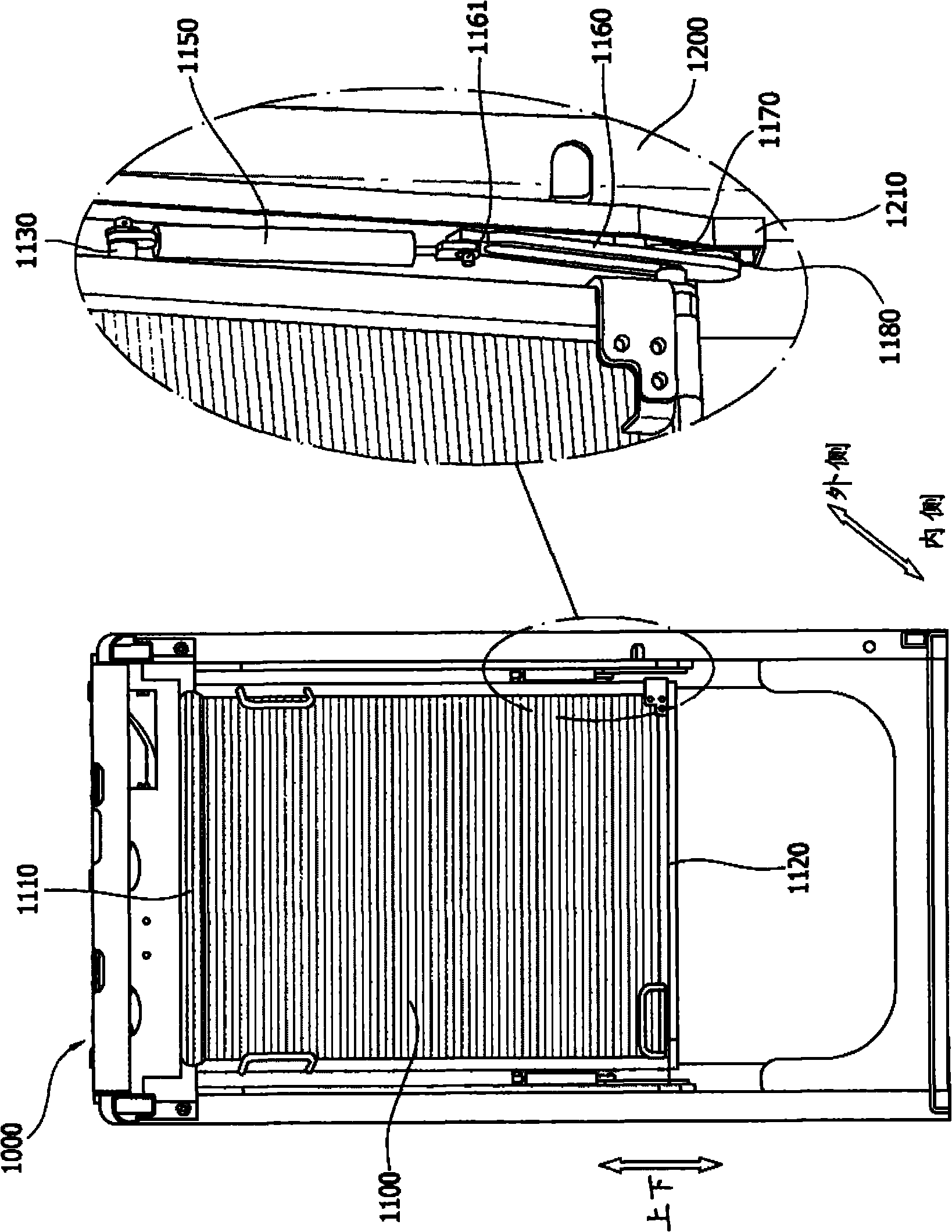
[0024] Generally speaking, heavy engineering equipment is also called civil machinery, which includes excavators, wheel loaders, forklifts, skid steer loaders, etc., and there are many types. Heavy engineering equipment can also consider the use of unmanned equipment, but most of the equipment currently in use uses the operator to directly board and perform the engineering method. This kind of manned equipment has the operator to directly recognize and quickly respond to the operating situation and can The advantages of changing conditions.
[0025] Take an excavator as an example. Excavators are civil engineering machinery used to excavate sand or rocks. They are used for homestead construction, road and drainage works, river reconstruction and water retaining works, tunnel and subway foundation works, mud and rock mining operations, woodland reclamation works, sand Equipment for various operations such as soil loading operations. Such an excavator may include: a lower traveling body driven by crawlers or wheels; an upper revolving body of a cab that is provided with a space that is rotatably coupled to the upper end of the lower traveling body and the driver can board; and Work equipment such as a boom, a forearm, and a bucket that are rotatably coupled in the forward direction of the revolving body. Generally speaking, the cab installed on the upper revolving body has a side door formed on the side of the door for the driver to enter and exit. However, in addition to such side doors recently, there are cases where operators need to enter and exit from the front of the cab depending on the operating environment, and in order to ensure visibility and two-way ventilation for confirming the work progress when heavy engineering equipment is performing lower-end operations. The way that the front window of the cab can be opened and closed has a front door in most cases.
[0026] Hereinafter, embodiments of the present invention related to such a front door switch will be described in detail with reference to the accompanying drawings.
[0027] figure 1 It is a perspective view showing a cab with heavy engineering equipment equipped with a front door, image 3 It is a structural diagram showing the front door of the heavy engineering equipment cab installed in an embodiment of the present invention, Figure 4 It is a structural diagram showing the main part of the connection state between the front door of the heavy engineering equipment cab and the cab frame installed in an embodiment of the present invention, Figure 5 A perspective view showing the main structure of the upper end of the front door of a heavy engineering equipment cab installed in an embodiment of the present invention. FIG. 6 is a perspective view showing the lower end of the front door when the front door of the heavy engineering equipment cab of an embodiment of the present invention is opened and closed. Three-dimensional view of the moving state.
[0028] Reference figure 1 and image 3 , The switch control device of the front door for heavy engineering equipment includes an elastic body 1150 and a guide plate 1160, and optionally includes a first lower guide roller 1170 and a second lower guide roller 1180.
[0029] Reference figure 1 and image 3 , The cab 1000 installed on heavy engineering equipment is a space for users to board, and it is a space for the operation and operation of heavy engineering equipment through various instrument panels, switches, and operating levers. In the above-mentioned cab 1000, in addition to the side door which is the main entrance door for the user, as described above, the front door 1100 is often provided. Since the conditions other than that for the above-mentioned cab 1000 are the same as the usual conditions, they will not be repeated here.
[0030] Reference figure 1 and image 3 The front door 1100 is attached to the cab 1000 of heavy engineering equipment, and is formed to be able to separate the front door 1100 from the cab frame 1200 corresponding to the frame of the cab 1000 and open and close inward of the cab 1000. For the side door of the above-mentioned cab 1000 (not marked with reference numerals), although there may be various embodiments, generally speaking, the way of rotating to the outside of the above-mentioned cab 1000 is mostly used. In contrast, as described above, the function of the front door 1100 is different from the side door (not marked with an icon). When it is intended for access or ventilation, it performs a function similar to the aforementioned side door (not marked with an icon), and the aforementioned front door 1100 can also perform a function of ensuring a visual field in order to confirm the progress of the work when the work is performed on site. Taking an excavator as an example, the ground at the location where the excavation work is performed is often lower than the ground where the excavator is located. In this case, it is particularly important for the user sitting in the cab 1000 to ensure the lower end side of the field of vision in order to perform work. For this reason, by lifting and fixing the aforementioned front door 1100, the work can be efficiently performed. Therefore, it is preferable that the front door 1100 is formed to be able to separate from the cab frame 1200 and open and close to the inner side of the cab 1000.
[0031] Reference image 3 and Figure 4 The aforementioned front door 1100 includes a front door upper shaft 1110 and a front door lower shaft 1120. The front door upper end shaft 1110 is formed at the upper end of the front door 1100, and when the front door 1100 is opened, it moves away from the cab frame 1200 and moves inwardly of the cab 1000. At the same time, the front door lower end shaft 1120 is formed at the lower end of the front door 1100, and moves upward along the guide portion 1210 of the cab frame 1200 when the front door 1100 is opened. The above-mentioned guide portion 1210 will be described later. In order to enable the user to ensure the front view, the front door 1100 is preferably made of glass, which can be the same as general automobile glass. In order to open and close the front door 1100 made of glass, the front door upper shaft 1110 is provided at the upper end of the front door 1100 and the front door lower shaft 1120 is provided at the lower end. The front door upper shaft 1110 and the front door lower shaft 1120 are used to bear the movement of the front door 1100 with a predetermined weight. Therefore, it is preferable to use a metal material with a certain degree of rigidity, or it may be made of and form the cab The frame of 1000 is an embodiment formed of the same material as the aforementioned cab frame 1200.
[0032] Reference image 3 and Figure 4 The guide portion 1210 is mounted on the cab frame 1200, and plays a role of allowing the front door upper shaft 1110 and the front door lower shaft 1120 to move along the track of the guide portion 1210 in a designed direction when they are swimming. Therefore, the guide portion 1210 is preferably installed on the entire path of the front door upper shaft 1110 and the front door lower shaft 1120 from the closed state of the front door 1100 to the most open state. The guide portion 1210 is preferably formed in the driver's cab frame 1200 close to the position where the front door 1100 is mounted, and it is preferably mounted in the driver's cab 1000 in the inner direction of the user riding. The guide portion 1210 is a space where the upper guide roller 1190, the first lower guide roller 1170, and the second lower guide roller 1180 move while rotating. The upper guide roller 1190, the first lower guide roller 1170, and the second lower guide roller 1180 will be described later.
[0033] Reference image 3 and Figure 4 One end of the elastic body 1150 is rotatably coupled to the first elastic body support portion 1130 provided at a predetermined distance upward from the lower end shaft 1120 of the front door. The first elastic body supporting portion 1130 may be formed in the front door 1100 to be further away from the front door lower end shaft 1120 and protrude in the left-right direction of the front door 1100. The first elastic support portion 1130 is preferably formed to include a roller (not shown) at a protruding portion so as to be able to move in the upward and downward directions along the guide portion 1210 for the movement accompanying the opening and closing operation of the front door 1100. One end of the elastic body 1150 is rotatably coupled to the first elastic body supporting portion 1130. This is because the position of the elastic body 1150 changes with the opening and closing operation of the front door 1100, and the opening and closing process of the front door 1100 will be described later. An end portion 1121 protruding in the left-right direction of the front door 1100 is formed on the lower end shaft 1120 of the front door. The space in which the front door lower end shaft 1121 swims in such a way that the front door lower end shaft 1120 can move with the opening and closing operation of the front door 1100 is the guide plate 1160.
[0034] Reference image 3 and Figure 4 In the guide plate 1160, a groove is formed long inwardly corresponding to the shape of the front door lower end shaft end 1121, so that the front door lower end shaft end 1121 operates according to the front door lower end shaft 1120 with the opening and closing of the front door 1100 The movement moves to the inside of the guide plate 1160. The guide plate 1160 is provided with a second elastic body support portion 1161 on the side corresponding to the position where the lower end shaft end portion 1121 of the front door is joined when the front door 1100 is closed. Similar to the first elastic body support portion 1130, the second elastic body support portion 1161 is a support portion that supports the elastic body 1150 so that the elastic body 1150 can rotate and swim. Therefore, the first elastic body supporting portion 1130 supports one end of the elastic body 1150, and the second elastic body supporting portion 1161 supports the other end of the elastic body 1150. Thus, one end of the elastic body 1150 is coupled to the first elastic body support portion 1130 to connect to the front door 1100, and the other end of the elastic body 1150 is coupled to the second elastic body support portion 1161 to connect to the guide plate 1160 .
[0035] Reference image 3 and Figure 4 The elastic body 1150 is formed in a long cylindrical shape, and can be combined with the first elastic body supporting portion 1130 and the second elastic body supporting portion 1161 to swim. The above-mentioned shape of the elastic body 1150 is only an example, and of course it can have various forms. The elastic body 1150 should be designed to lift the front door 1100 upward when the front door 1100 is opened so that the user can easily lift it, and when the front door 1100 is closed, it should lift upward to offset the gravity so that the front door 1100 does not Falling quickly due to gravity. The above-mentioned elastic body 1150 may be considered as an embodiment in which an elastic body such as a spring is also used as a buffer force due to a change in gas volume. In this case, the above-mentioned elastic body 1150 may be a structure in which a mechanical elastic body such as a spring is provided inside and a fluid such as nitrogen or compressed air is filled in and sealed. In this case, when the front door 1100 is opened, the restoring force of the compressed mechanical elastic body and the volume restoring force of the fluid compressed into a smaller volume can easily lift the front door 1100 upward. On the contrary, when the front door 1100 is closed, the elongated mechanical elastic body and the fluid with a larger volume are suddenly compressed by the front door 1100 falling due to gravity, thereby reducing the falling speed of the front door 1100, thereby preventing the rapid Equipment damage and safety accidents caused by falling.
[0036] Reference image 3 and Figure 4 The aforementioned front door 1100 may include a first lower guide roller 1170 and a second lower guide roller 1180. The first lower end guide roller 1170 is formed so that the lower end shaft end portion 1121 of the front door penetrates and swims in a play space formed inside the guide plate 1160. The lower end shaft end portion 1121 of the front door penetrates and swims in the play space of the guide plate 1160, and is coupled with the first rotating shaft 1171 forming the first lower end guide roller 1170. The lower shaft end portion 1121 of the front door moves up and down on the guide plate 1160 following the opening and closing action of the front door 1100, and the first lower guide roller 1170 rotates on the basis of the first rotating shaft 1171 and moves along the guide plate 1160. The trajectory following the guide part 1210 swims in the guide part 1210. The second lower guide roller 1180, when the guide plate 1160 moves with the movement of the front door lower shaft 1120 and the elastic body 1150, rotates and swims on the basis of the second rotating shaft 1181 connected to the guide plate 1160. move. The formation position of the second rotating shaft 1181 is preferably lower than the position where the first rotating shaft 1171 is formed. The second lower end guide roller 1180 is formed to rotate with the second rotating shaft 1181 as a reference and to swim inside the guide portion 1210.
[0037] Reference Figure 5 When the front door 1100 is opened and closed, the movement of the upper shaft 1110 of the front door can be confirmed. When the front door 1100 is closed and fixed at the guide portion 1210, the upper guide roller 1190 provided on the upper shaft 1110 of the front door should be fixed and not move. To this end, a fixing groove 1211 can be provided on the above-mentioned guide portion 1210, refer to Figure 5 It can be seen that as the cab frame 1200 is curved from the front surface of the cab 1000 to the top surface, the guide portion 1210 is also formed to be curved in the direction in which the cab frame 1200 is formed. If the upper guide roller 1190 is fixed at the bend of the guide portion 1210, the front door upper shaft 1110 connected to the upper guide roller 1190 is fixed, and the front door 1100 will not move or vibrate. Therefore, the fixing groove 1211 is preferably formed so as to be recessed in the guide portion 1210 toward the outside of the cab 1000. When opening the front door 1100, the upper guide roller 1190 fixed in the fixing groove 1211 can be moved along the track of the guide portion 1210 to pull the front door 1100 inward and then upward.
[0038] FIG. 6 shows the movement of the front door 1100 at the lower end when the front door 1100 is opened and closed. Figure 6a This indicates a state where the front door 1100 is closed and sealed. Figure 6b In the process of opening the front door 1100, the elastic body 1150 is loosened and extends upward, whereby the lower end shaft end portion 1121 of the front door uses the first lower end guide roller 1170 to move upward along the guide plate 1160. . Figure 6c Indicates that the front door 1100 is compared Figure 6b When the guide plate 1160 is further pushed up and the guide plate 1160 is moved upward and completely opened, the second lower end guide roller 1180 is moved upward along the guide portion 1210. When closing the front door 1100, it is sufficient to proceed in the reverse order of the opening process described above. The length of the play space of the guide plate 1160 is preferably formed to be close to the difference between the length of the elastic body 1150 measured when the front door 1100 is opened and the length of the elastic body 1150 measured when the front door 1100 is closed. This is because the guide plate 1160 provides a play space for the shaft end portion 1121 of the lower end of the front door according to the length change caused by the relaxation and contraction movement of the elastic body 1150. However, when referring to the drawings, the angle between the elastic body 1150 and the ground surface may be different from the angle between the guide plate 1160 and the ground surface, and the angle floats with the opening degree of the front door 1100. Therefore, the guide plate The length of the play space of 1160 is preferably formed to be close to the difference between the length of the elastic body 1150 measured when the front door 1100 is opened and the length of the elastic body 1150 measured when the front door 1100 is closed, rather than the same.
[0039] The technical idea should not be limited to the above-mentioned embodiments of the present invention and explained. Needless to say, the scope of application is relatively broad, and various modifications can be implemented at the level of those skilled in the art without exceeding the gist of the present invention claimed in the claims. Therefore, such modifications and changes are self-evident to those skilled in the art, and all belong to the protection scope of the present invention.
PUM


Description & Claims & Application Information
We can also present the details of the Description, Claims and Application information to help users get a comprehensive understanding of the technical details of the patent, such as background art, summary of invention, brief description of drawings, description of embodiments, and other original content. On the other hand, users can also determine the specific scope of protection of the technology through the list of claims; as well as understand the changes in the life cycle of the technology with the presentation of the patent timeline. Login to view more.