
Antenna impedance matching device and method

A technology of antenna impedance and matching device, which is applied in the field of communication, can solve the problems of complex and redundant matching forms, fixed matching forms, weak adjustment ability, etc., and achieve the effect of solving the single impedance matching mode

Active Publication Date: 2016-04-13
ZTE CORP
View PDF4 Cites 0 Cited by
  • Summary
  • Abstract
  • Description
  • Claims
  • Application Information

AI Technical Summary

Problems solved by technology

[0009] However, the above methods have some disadvantages. For example, the matching form of mode 1 is fixed, which is not conducive to multi-band adjustment; in mode 2, only different matching forms can be selected, and the matching forms are complex and redundant, and for each combination form, they are also quite independent and fixed. There is no fine-tuning function; method 3 provides fixed matching devices for each antenna, which is only used in multi-antenna RF systems; method 4 is based on traditional variable capacitance adjustment impedance matching, the adjustment range is narrow, and the adjustment ability is weak, which cannot meet the current requirements. Matching requirements for multiple applications

Method used


Image

  • Antenna impedance matching device and method
  • Antenna impedance matching device and method
  • Antenna impedance matching device and method

Examples


Embodiment Construction

[0020] Hereinafter, the present invention will be described in detail with reference to the drawings and examples. It should be noted that, in the case of no conflict, the embodiments in the present application and the features in the embodiments can be combined with each other.

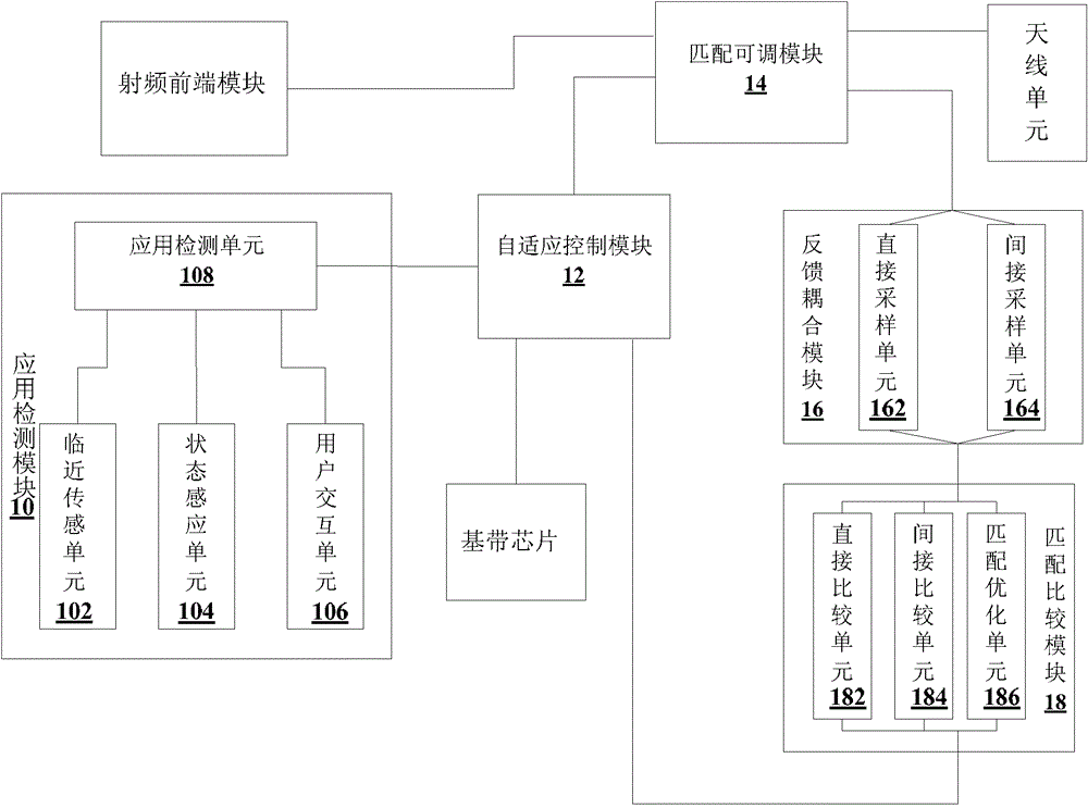
[0021] figure 1 is a structural block diagram of an antenna impedance matching device according to an embodiment of the present invention. Such as figure 1 As shown, the antenna impedance matching device according to the embodiment of the present invention includes:

[0022] The application detection module 10 is used to detect the current state of the terminal antenna, and output a matching adjustment signal according to the above state;

[0023] An adaptive control module 12, connected to the application detection module 10, for controlling the matching adjustment process in response to the matching adjustment signal;

[0024] The matching adjustable module 14 is connected to the adaptive contr...


PUM


Abstract

The present invention discloses an antenna impedance matching device and method. The device includes: an application detection module for detecting the current state of a terminal antenna, and outputting a matching adjustment signal according to the state; an adaptive control module for responding to the above The matching adjustment signal controls the matching adjustment process; the matching adjustment module is used for matching and adjusting the antenna impedance through the impedance matching network corresponding to the matching adjustment signal under the control of the adaptive control module. The technical solution provided by the present invention solves the problem of a single impedance matching mode in the prior art, thereby achieving the effect of performing differential matching for various application states of the terminal.

Description

technical field [0001] The present invention relates to the communication field, in particular to an antenna impedance matching device and method. Background technique [0002] The performance of the antenna directly determines the strength of the transmitted signal. When debugging the antenna, impedance matching and VSWR (Voltage Standing Wave Ratio, Voltage Standing Wave Ratio) have a great influence on the performance of the antenna. Especially TRP (Total Radiated Power, total radiated power) and TIS (Total Isotropic Sensitivity, total omnidirectional sensitivity) and antenna efficiency are very important indicators of mobile phones, which affect the performance of the whole machine and determine the success or failure of the product. [0003] Impedance matching refers to a working state in which the load impedance and the internal impedance of the excitation source are mutually matched to obtain the maximum power output. It reflects the power transfer relationship betwee...

Claims


Application Information

Patent Timeline
Patent Type & Authority Patents(China)
IPC IPC(8): H04B1/18H01Q1/24
CPCH04B1/0458H04B1/18H01Q1/50
Inventor 沈少武
Owner ZTE CORP
Learn More