Indoor machine of air conditioner

A technology for indoor units and air conditioners, applied in the field of indoor units, can solve the problems of inability to achieve wide-angle wind direction guidance, inability to ignore air volume loss, and narrow adjustment range of wind direction in the left and right directions.

Active Publication Date: 2011-07-13
TOSHIBA CARRIER CORP
View PDF9 Cites 8 Cited by
  • Summary
  • Abstract
  • Description
  • Claims
  • Application Information

AI Technical Summary

Problems solved by technology

[0005] In recent years, with the increase of continuous spaces such as living room, dining room and kitchen, the requirements for wind direction characteristics in the up and down directions and left and right directions are increasing. wind direction
In addition, after changing the wind direction in the left and right directions, the wind direction in the up and down direction is changed, so two losses occur when the wind direction is changed, and the air volume loss cannot be ignored.

Method used


Image

  • Indoor machine of air conditioner
  • Indoor machine of air conditioner
  • Indoor machine of air conditioner

Examples


Embodiment Construction

[0032] Embodiments of the present invention will be described below with reference to the drawings.

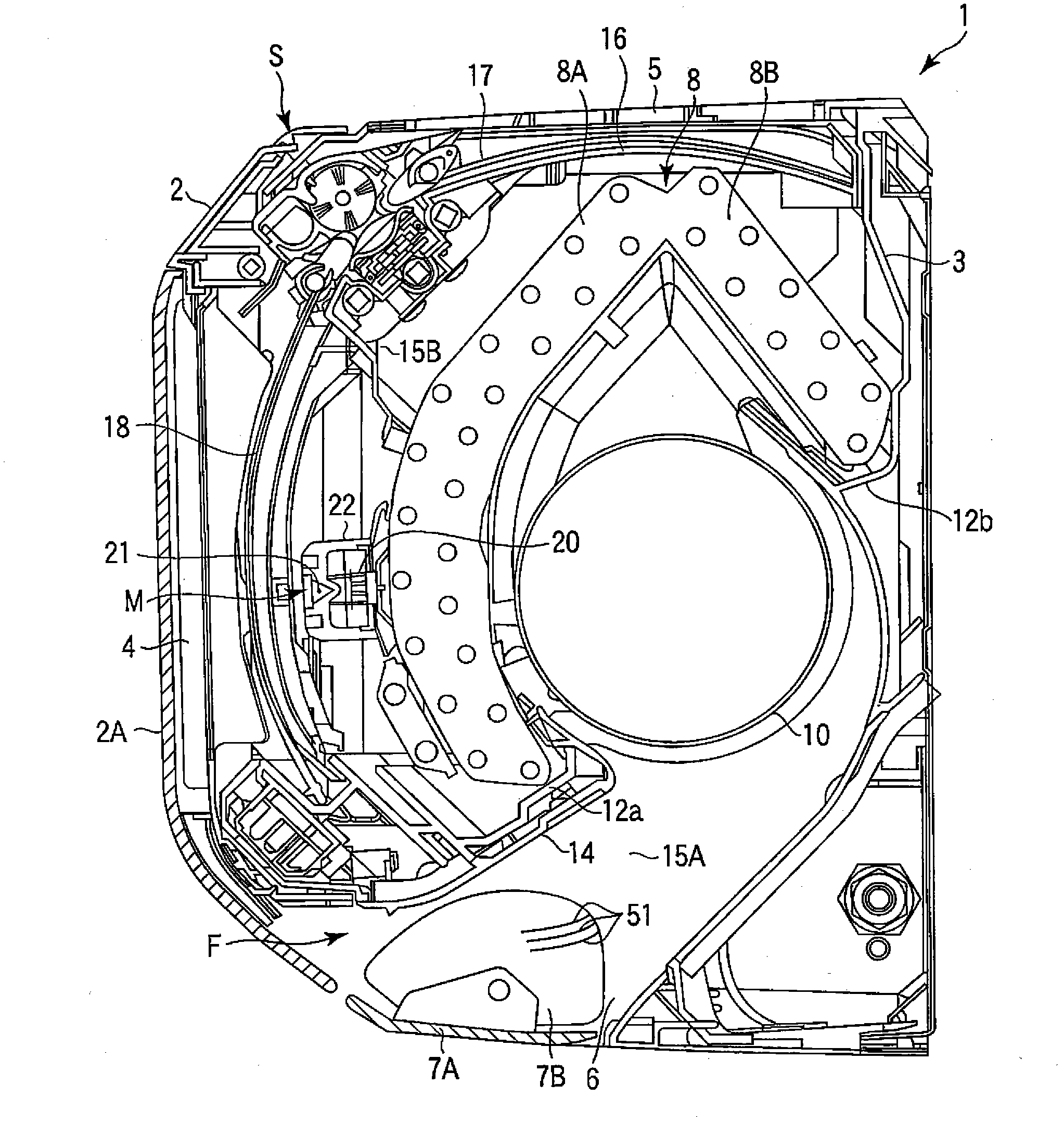
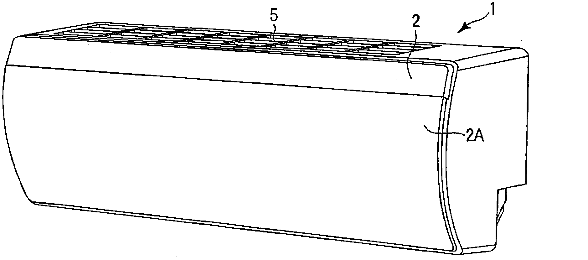
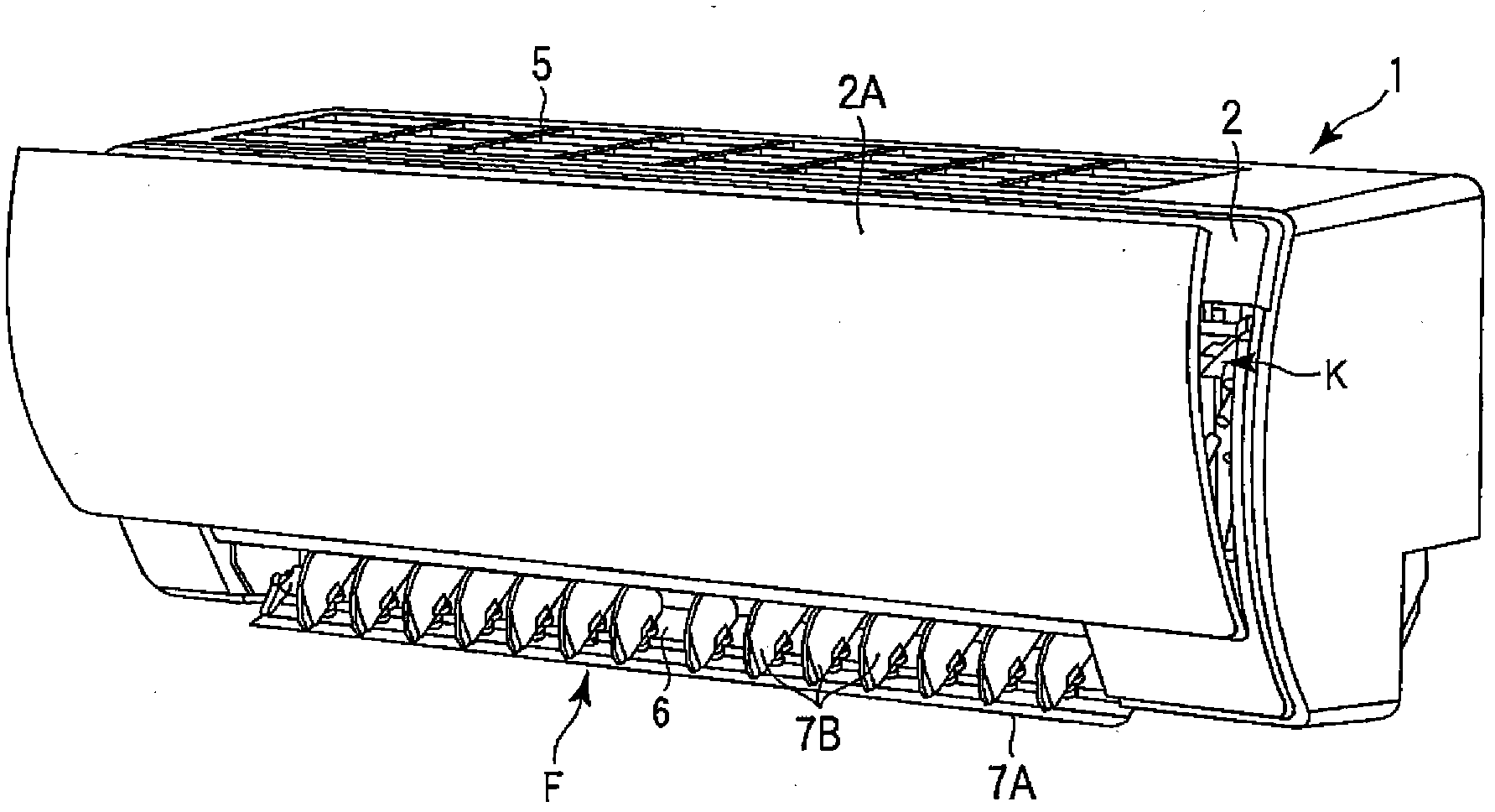
[0033] figure 1 It is a longitudinal sectional view schematically showing the indoor unit of the air conditioner when the refrigeration cycle operation is stopped, figure 2 is a perspective view showing the appearance of the indoor unit when the operation is stopped, image 3 It is a perspective view of the appearance of the indoor unit during refrigeration cycle operation (in addition, parts not marked in the description are not shown, and some parts are shown but not marked).

[0034] The indoor unit body 1 is composed of a front panel 2 constituting a front casing and a rear body 3 constituting a rear casing, and is formed in a horizontally elongated shape in a left-right width direction with respect to an up-down direction. A front suction port 4 is opened on a part of the front side of the indoor unit main body 1, and a movable panel 2A supported by an opening and clos...


PUM


Abstract

A wind direction guide device (F) installed at a blowout hole (6) comprises a vertical wind direction louver (7A) for controlling the vertical blowout direction of a heat exchange air and a lateral wind direction louver (7B) attached to the vertical wind direction louver (7A) and controlling the lateral blowout direction of the heat exchange air. The lateral wind direction louver (7B) is longer in the depth direction than in the vertical direction and equal to or longer in the depth direction than the length of the vertical wind direction louver (7A) in the depth direction. The vertical wind direction louver (7A) is set in a generally horizontal attitude and the lateral wind direction louver (7B) is positioned on the front surface side of the vertical wind direction louver (7A) for guiding the horizontal blowout. The vertical wind direction louver (7A) is set generally vertical attitude and the lateral wind direction louver (7B) is positioned on the rear surface side of the vertical wind direction louver (7A) for guiding the downward blowout. Since the guiding of the horizontal blowout during the cooling operation and the guiding of the downward blowout during the heating operation can be surely and efficiently changed over, the wind direction guiding characteristic is improved, and the heat exchange air can be smoothly circulated.

Description

technical field [0001] The present invention relates to an indoor unit of an air conditioner, and particularly relates to an improvement of a wind direction guide device provided on an air outlet to blow out and guide heat exchange air into the room. Background technique [0002] An air conditioner composed of an indoor unit and an outdoor unit has a wind direction guide device for blowing out and guiding heat-exchanged air such as cold air obtained by the indoor unit into the room. This wind direction guide device is composed of: left and right wind direction louvers, up and down wind direction louvers provided on the air outlet of the indoor unit body, a driving source and a drive mechanism for driving the left, right, up and down wind direction louvers. [0003] Usually, as shown in JP-A-5-52386, left and right wind direction louvers are provided on the blowing ventilation path formed on the downstream side of the blower, and up and down wind direction louvers are provide...

Claims


Application Information

Patent Timeline
Patent Type & Authority Applications(China)
IPC IPC(8): F24F13/15F24F13/20
CPCF24F2001/0048F24F13/15F24F1/0011F24F1/0057
Inventor 和田宏二竹谷伸行东地广明仙道要小泽哲朗清水克浩杉崎智子渡边诚
Owner TOSHIBA CARRIER CORP
Why Eureka
Try Eureka