Sine wave inverting power supply

A sine wave, inverter technology, applied in the field of power electronic technology inverter

Inactive Publication Date: 2011-08-17
杨韬
View PDF1 Cites 0 Cited by
  • Summary
  • Abstract
  • Description
  • Claims
  • Application Information

AI Technical Summary

Problems solved by technology

There is no device that uses photoele

Method used


Image

  • Sine wave inverting power supply
  • Sine wave inverting power supply

Examples


Embodiment Construction

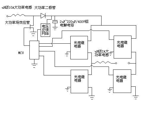
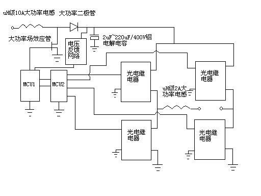
[0005] The main components of the sine wave inverter are uH-class 10A high-power inductors, high-power FETs, power diodes, MCU, uH-class 2A high-power inductors, voltage feedback networks, 2uF~220uF / 400V aluminum electrolytic capacitors and photoelectric relays. Such as figure 1 shown. The uH grade 10A high-power inductor is connected to the high-power FET, the high-power FET is connected to the power diode, the high-power FET is connected to the MCU, and the power diode is connected to the 2uF~220uF / 400V aluminum electrolytic capacitor. Each photoelectric relay of the full bridge composed of MCU and photoelectric relays is connected, the full bridge composed of photoelectric relays is connected with 2uF~220uF / 400V aluminum electrolytic capacitors, the output end of the full bridge composed of uH class 2A high-power inductors and photoelectric relays One end is connected, the voltage feedback network is connected to the MCU, the voltage feedback network is connected to the 2u...


PUM


Abstract

The invention relates to a sine wave inverter which comprises a uH-grade 10A high-power inductor, a high-power field-effect tube, a power diode, an MCU (Microprogram Control Unit), a uH-grade 2A high-power inductor, a voltage feedback network, a 2uF-220uF/400V aluminum electrolytic capacitor and a photoelectric relay. The sine wave inverter has the converting efficiency of 99 percent and low cost, saves energy and completely replaces the traditional inverter product with low converting efficiency.

Description

technical field [0001] The invention belongs to the field of power electronic technology inverters. Background technique [0002] In the field of inverters, the conversion efficiency of sine wave inverters is generally around 80%. There is no device that uses photoelectric devices to realize inverters. However, for ordinary inverters using MOSFET power field effect tubes, since the device itself consumes a lot of power, the conversion efficiency will not be affected by more than 80%. Contents of the invention [0003] The conversion efficiency of the inverter is a crucial technical issue. The higher the conversion efficiency, the more energy can be saved. The current conversion efficiency below 80% can no longer meet the needs of the society. In order to solve the above-mentioned technical problems, the present invention adopts the following technical scheme: use high-power photoelectric relays to form an inverter bridge, use MCU as the controller, and the MCU also reali...

Claims


Application Information

Patent Timeline
IPC IPC(8): H02M7/54
Inventor 杨韬
Owner 杨韬
Why Eureka
Try Eureka