
Engine for working utilizing regenerated physical energy source

An engine and work-making technology, applied in the direction of engines, elastic engines, machines/engines, etc., can solve problems that affect the service life of batteries, endanger human health, and easily damage battery plates of batteries

Inactive Publication Date: 2013-01-30
盐城合能机电科技发展有限公司
View PDF0 Cites 0 Cited by
  • Summary
  • Abstract
  • Description
  • Claims
  • Application Information

AI Technical Summary

Problems solved by technology

These power source machines all use the mechanical power source obtained from fuel energy conversion, so they will emit a large amount of exhaust gas and seriously endanger human health. People are eager to have a power machine that uses green energy as the power source. Power source, since starting the motor requires a lot of current, and some motors need to be started frequently, it is very easy to damage the battery plate of the battery and affect the service life of the battery, and the battery power reserve is limited, and frequent startup acceleration requires consumption A large amount of electric energy greatly reduces the use after one charge. At present, flywheels and springs are mainly used as energy storage devices. Because they cannot generate energy by themselves, they are not used in power source machines.

Method used


Image

  • Engine for working utilizing regenerated physical energy source
  • Engine for working utilizing regenerated physical energy source
  • Engine for working utilizing regenerated physical energy source

Examples


Embodiment Construction

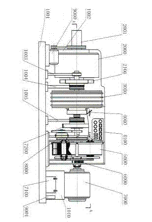
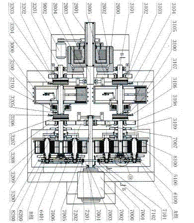
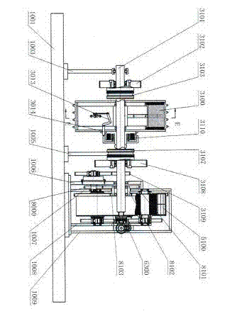
[0135] The present invention provides a schematic cross-sectional view of the main view such as figure 1 As shown, its A-A sectional view is shown as figure 2 As shown, the B-B section view is shown as image 3 As shown, the C-C section view is shown as Figure 4 As shown, the D-direction sectional view is shown in 5, and the E-E sectional view is shown in Figure 6 , the schematic diagram of the principle of the F-direction transmission relationship is shown in Figure 7 , the schematic diagram of the transmission principle of the layout structure of the activation transmission system is as follows Figure 8 , the schematic diagram of the control principle of the regenerative physical energy engine is shown in Figure 9 Shown is an engine that uses regenerative physical energy to do work, and the present invention will be described in detail below in conjunction with the accompanying drawings.

[0136] As a specific embodiment of the present invention, the present inven...


PUM


Abstract

The invention provides an engine for doing work utilizing a regenerated physical energy source. The engine comprises an engine base, at least two groups of external applied power source working reservation energy pools and a working speed-increasing transmission mechanism, wherein the engine base is provided with primary power output shafts and primary power shafts which are corresponding with each group of external applied power source working reservation energy pool; and each primary power output shaft is provided with a hard solid constant-volume constant-value object material diameter-variable flywheel. According to the invention, through grouping design of two energy storage devices of a flat spiral spring construction element which is made from a spring steel material and a mechanical construction element flywheel, and the combination of power supplying machines of the regenerated power supply electricity energy, then a corresponding electrical control device is connected, thus a regenerated physical energy source engine capable of doing work continuously is assembled, through the design, constant-volume constant-value working energy can be added in a dispersion and subsection mode, thus the working of the continuous operation for the engine can be satisfied.

Description

technical field [0001] The invention relates to the field of automobile driving devices, in particular to an engine using regenerative physical energy to do work. Background technique [0002] A heat engine is a power machine that converts the chemical energy of fuel into internal energy and then into mechanical energy. It usually uses gas as a working medium (the medium that transmits energy is called a working medium), and then uses the gas to expand when heated to do work. There are two types of heat engines, one is internal combustion engines, including gasoline engines, diesel engines, gas engines, gas turbines, jet engines, and rocket engines; the other is external combustion engines, including steam engines and steam turbines. These power source machines all use the mechanical power source obtained from fuel energy conversion, so they will emit a large amount of exhaust gas and seriously endanger human health. People are eager to have a power machine that uses green e...

Claims


Application Information

Patent Timeline
Patent Type & Authority Patents(China)
IPC IPC(8): F03G1/00F03G1/02
Inventor 杨永明
Owner 盐城合能机电科技发展有限公司
Learn More