Position detection system and position detection method

A detection system and location information technology, which is applied in diagnostic recording/measurement, in-vivo radio detectors, medical science, etc., and can solve problems such as poor observation ability and the inability of capsule endoscope to move in the subject.

Inactive Publication Date: 2011-09-14
OLYMPUS CORP
View PDF6 Cites 4 Cited by
  • Summary
  • Abstract
  • Description
  • Claims
  • Application Information

AI Technical Summary

Problems solved by technology

[0003] This type of capsule endoscope itself usually cannot move within the subject, but moves within the subject through the peristaltic movement of the subject's digestive organs, etc.
Therefore, compared with an endoscope, such as a fiberscope, where the operator can freely select the observation site to some extent, the observation ability may be poor.

Method used


Image

  • Position detection system and position detection method
  • Position detection system and position detection method
  • Position detection system and position detection method

Examples


Embodiment approach 1

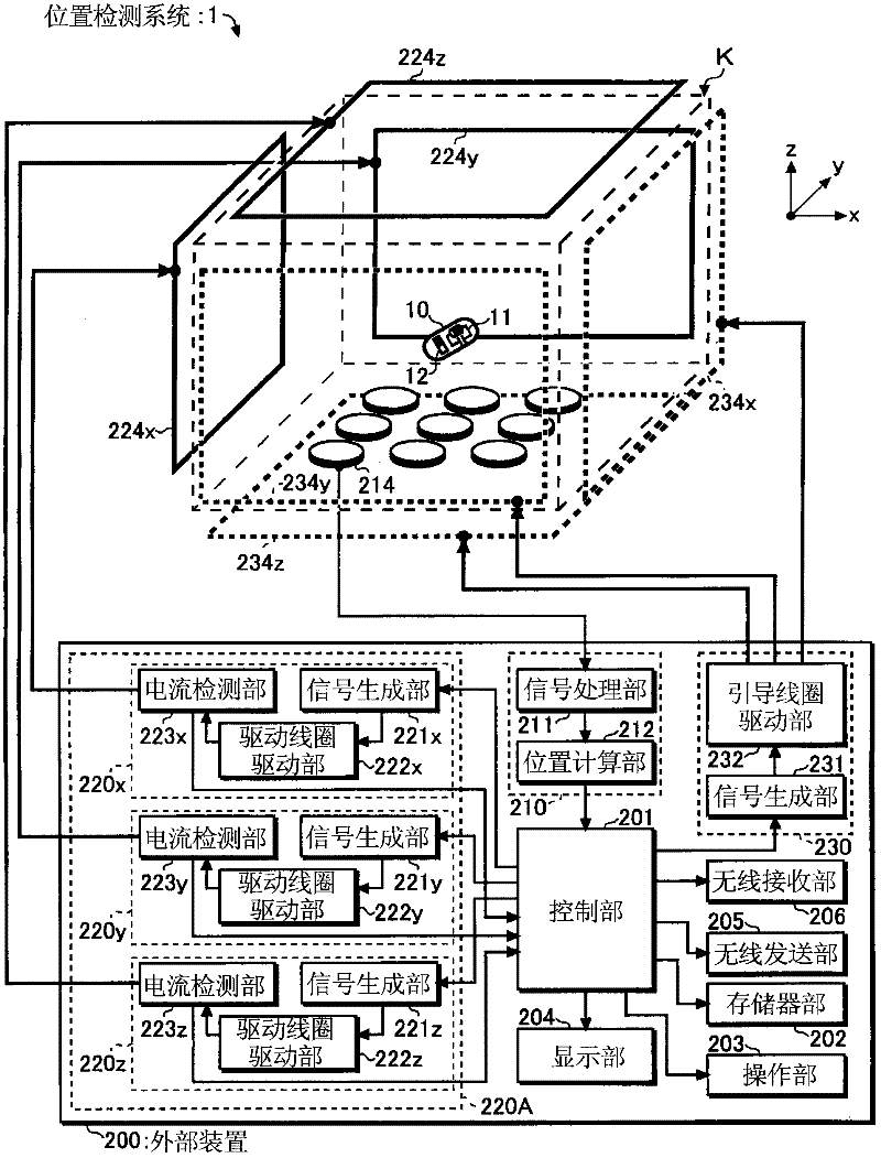
[0051] Next, the configuration and operation of the position detection magnetic guidance system 1 according to Embodiment 1 of the present invention will be described in detail using the drawings. In addition, this embodiment is for avoiding the need for the driving magnetic field generating device 220A (refer to figure 1 ) increases the error included in the position detection result derived when the feedback control is performed, thereby enabling stable and accurate position detection in the position detection magnetic guidance system 1 using the feedback control.

[0052] (structure)

[0053] figure 1 It is a schematic diagram which shows the schematic structure of the position detection magnetic guidance system 1 of this embodiment. like figure 1 As shown, the position detection magnetic guidance system 1 is provided with a detection space K and an external device 200, the detection space K accommodates the subject to be introduced into the capsule medical device 10 ...

Deformed example 1

[0113] In addition, in order to derive more accurate position and direction information, the position detection magnetic guidance system 1 of this embodiment is configured to take the average value of the detection signal (FFT data) output from the signal processing unit 211 of the position derivation unit 210, and calculate the position. The unit 212 calculates the position and direction information using the averaged detection signal (FFT data), or is configured to average the position and direction information output from the position derivation unit 210 in the control unit 201, etc., and various out of shape. Next, a case of averaging detection signals (FFT data) will be described as Modification 1 of the present embodiment. In addition, in the description below, the detection signal (FFT data) is simply referred to as FFT data.

[0114] Figure 8 It is a flowchart showing the general operation of the position calculation unit 212 in the first modification. Furthermore,...

Deformed example 2

[0122]In addition, for example, the number of data sets n in Modification 1 of the present embodiment can be reduced even when position detection is performed stably. This is because if each FFT data (or position and direction information) is correct, correct position and direction information can be acquired even without averaging a larger number of FFT data (or position and direction information).

[0123] Also, for example, the number n of data sets can be increased even when the position detection is unstable. This is because the accuracy of the derived position and orientation information is improved by averaging more FFT data (or position and orientation information).

[0124] In addition, the state where position detection is performed stably refers to a state where the absolute value of the difference between the previous amplitude value and the new amplitude value is equal to or less than the difference reference value 202d continues for a long period of time. In add...


PUM


Abstract

An external device (200) arranged out of a detection space K in a position detection magnetic induction system (1) includes: a signal generation unit (221) which outputs a drive signal of a resonance frequency F0; a drive coil drive unit (222) which current-amplifies the drive signal generated by the signal generation unit (221); a drive coil (224) which forms a drive magnetic field in the detection space K in accordance with the drive signal inputted from the drive coil drive unit (222); and a control unit (201) (drive magnetic field generation control unit 201A: see Fig. 6) which detects stability of the drive magnetic field formed by the drive coil (224) and controls the signal generation unit (221) in accordance with the detected stability.

Description

technical field [0001] The present invention relates to a position detection system and a position detection method, in particular to a position detection system and a position detection method for detecting the position of a capsule-type in-subject introduction device introduced into a subject by using a magnetic field. Background technique [0002] In recent years, a capsule-type subject-introduction device (hereinafter referred to as a capsule endoscope) equipped with an imaging device has been developed. For example, a capsule endoscope is orally introduced into a subject to take images of the subject, and wirelessly transmits the obtained image (hereinafter referred to as an in-subject image) to an external device placed outside the subject. The operator visually confirms the in-vivo images of the subject received by the external device, and can diagnose the symptoms of the subject and the like. [0003] Such a capsule endoscope itself is generally unable to move withi...

Claims


Application Information

Patent Timeline
IPC IPC(8): A61B1/00A61B5/07
CPCA61B1/041A61B5/7257A61B5/06A61B5/0031A61B1/00158A61B5/062A61B1/00006A61B1/00016A61B1/0684A61B1/0655
Inventor 木村敦志佐藤良次千叶淳饭田隆广
Owner OLYMPUS CORP
Why Eureka
Try Eureka