Electric working machine

A working machine, electric technology, applied in the direction of motor control, electronic commutation motor control, electric pruning saw, etc., can solve the problem of unable to detect the rotation position, unable to reach the detection level of the rotation position, etc., to simplify the structure and reduce costs Effect

Pending Publication Date: 2019-10-15
MAKITA CORP
View PDF1 Cites 0 Cited by
  • Summary
  • Abstract
  • Description
  • Claims
  • Application Information

AI Technical Summary

Problems solved by technology

[0006] However, since the induced voltage is proportional to the number of revolutions of the brushless motor, when the brushless motor rotate

Method used


Image

  • Electric working machine
  • Electric working machine
  • Electric working machine

Examples


no. 1 Embodiment approach

[0083] In this embodiment, a lawn mower will be described as an example of an electric working machine.

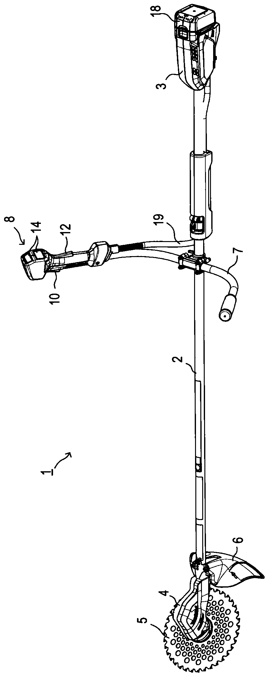
[0084] Such as figure 1 As shown, the electric working machine 1 of this embodiment is a lawn mower including a main pipe 2 , a control unit 3 , a drive unit 4 and a handle 7 . The main pipe 2 is formed in a long and hollow rod shape. A control unit 3 is provided on the rear end side of the main pipe 2 , and a drive unit 4 is provided on the front end side of the main pipe 2 .

[0085] The rotary knife 5 is attached to the drive unit 4, and the rotary knife 5 is detachable and rotatable. Rotary knife 5 is used for cutting objects such as cutting grass, trail trees, figure 1 The rotary knife shown is a so-called saw blade.

[0086] That is, the rotary blade 5 is made of metal, has a disk-like shape, and has serrated teeth formed over the entire outer circumference. A hard cutter head is installed on the top of each tooth.

[0087] A shroud 6 is provided on the front e...

no. 2 Embodiment approach

[0222] In the first embodiment, when the motor 20 is driven at a low speed by the combination PWM drive, the rotor position is detected based on the magnitude relationship of the current value due to switching of the switch combination.

[0223] However, the rotor position can be detected based on the relationship between the magnitude of the inductance due to switching of the switch combination.

[0224]Therefore, in order to detect the rotor position, it is not necessary to sequentially switch the switch combination to combination 1 and 2 to detect the current value when the motor 20 is driven at a low speed as in the first embodiment, but to measure the current value until it reaches a predetermined threshold. time spent.

[0225] Therefore, next, in this embodiment, an electric working machine that detects the rotor position based on the magnitude relationship of the time by measuring the time until the current value reaches a predetermined threshold value will be describe...


PUM


Abstract

The invention provides an electric working machine that includes a brushless motor capable of detecting a rotational position of the brushless motor when the brushless motor is rotating at a low speedwithout using a rotation sensor and at a low cost. The electric working machine includes an inverter and a controller. The controller switches a current conduction pattern via the inverter and performs a PWM control of a conduction current to a brushless motor. The controller includes switching patterns as the current conduction pattern switched for every commutation timing. The switching patterns include different on and off states for different switching elements. The controller sequentially switches a switching pattern synchronously with a period of the PWM control, detects a rotational position of a brushless motor from a magnitude relation between inductances of the brushless motor produced by switching the switching pattern, and sets the commutation timing.

Description

technical field [0001] The present invention relates to an electric working machine including a brushless motor as a power source. Background technique [0002] The brushless motor needs to switch the energization pattern of the stator coil every predetermined rotation angle of the rotor. Therefore, an electric working machine including a brushless motor has a detection unit for detecting the rotational position of the brushless motor (specifically, the rotor). [0003] As the detection unit, generally known are a rotation sensor that generates a signal based on the rotation angle of the rotor, or a sensorless detection unit that detects the rotational position based on the induced voltage generated by the rotation of the rotor. [0004] Furthermore, according to the sensorless detection unit adopting the structure that detects the rotational position of the brushless motor (in other words, the rotor) based on the induced voltage, as long as the voltage of each phase termin...

Claims


Application Information

Patent Timeline
IPC IPC(8): H02P6/08H02P6/185
CPCH02P6/08H02P6/185H02P6/186H02P29/024H02P6/24H02P2203/03A01D34/78A01G3/088H02P6/153A01D34/90H02P6/28
Inventor 西村真澄伊藤义照
Owner MAKITA CORP
Why Eureka
Try Eureka