

Motor drive apparatus
a technology of motor drive and motor stopper, which is applied in the direction of motor/generator/converter stopper, electronic commutator, dynamo-electric converter control, etc., can solve the problems of affecting the operation of the motor. , to achieve the effect of reducing the interruption period of each drive current, reducing noise, and stable position detection
- Summary
- Abstract
- Description
- Claims
- Application Information
AI Technical Summary
Benefits of technology
Problems solved by technology
Method used
Image

Examples
embodiments
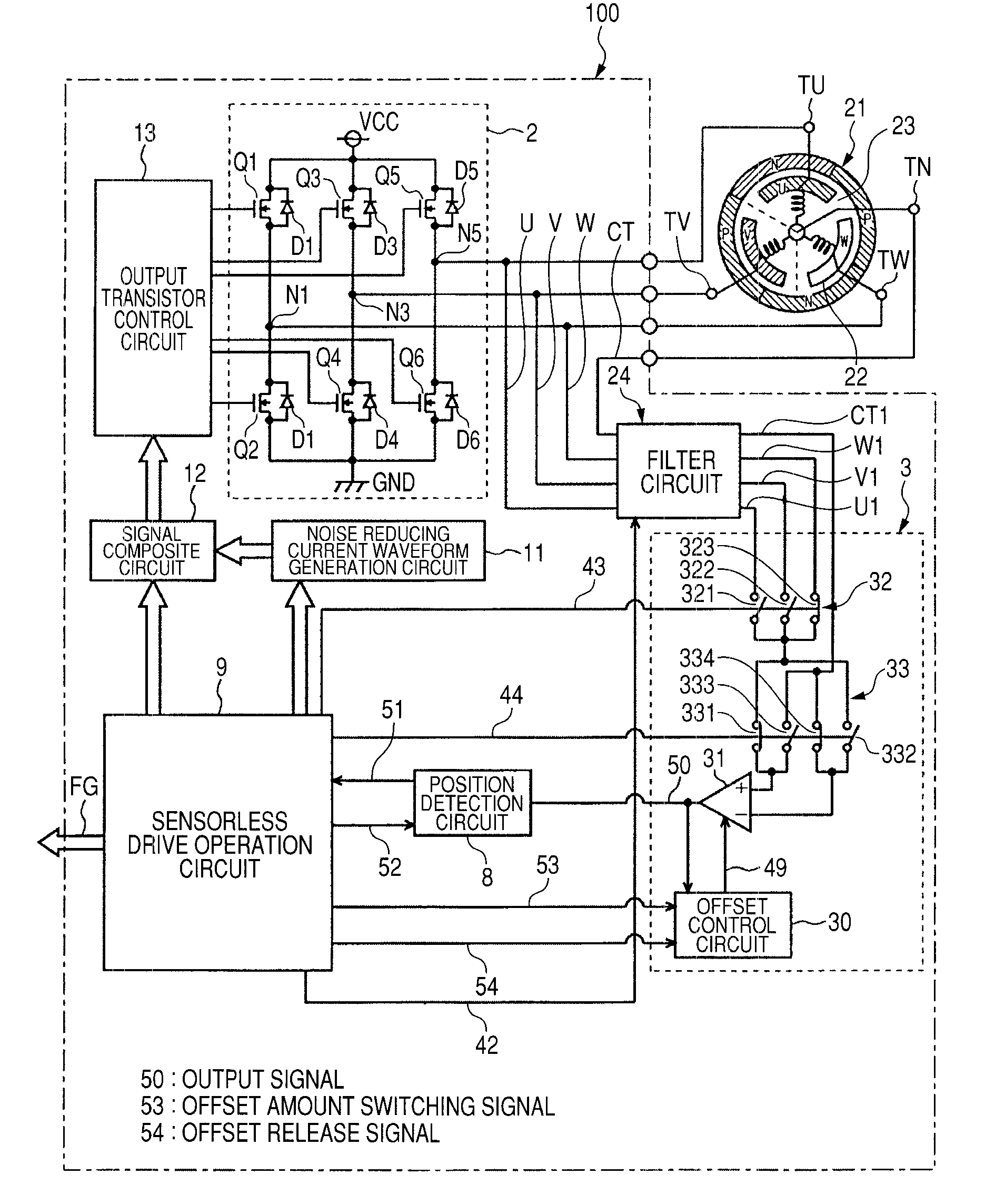
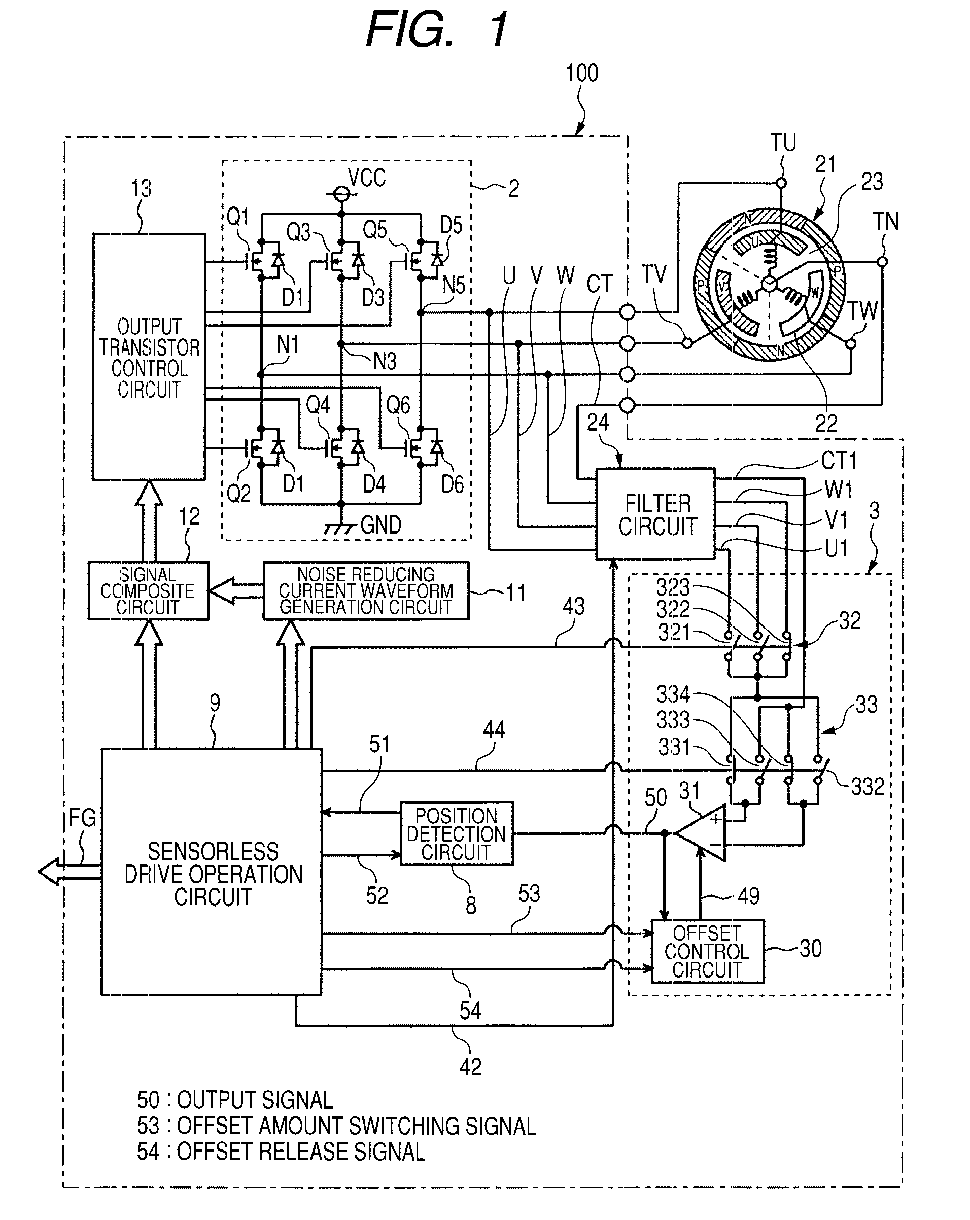
[0027]FIG. 1 is a block diagram showing a configuration of a motor drive apparatus 100 illustrative of an embodiment according to the present invention. As shown in FIG. 1, the motor drive apparatus 100 includes an output circuit 2, a filter circuit 24, a comparison circuit 3 (voltage comparison unit), a position detection circuit 8, a sensorless drive operation circuit 9 (drive operation unit), a noise reducing current waveform generation circuit 11, a signal composite circuit 12 and an output transistor control circuit 13. The motor drive apparatus 100 drives a 3-phase brushless motor 21 without using a Hall sensor. Incidentally, the motor drive apparatus 100 is formed as one IC (Integrated Circuit).
[0028]The 3-phase brushless motor 21 has a stator 22 and a rotor 23 rotatably provided therearound. The stator 22 includes Y-coupled coils of an U-phase, a V-phase and a W-phase. One ends of the coils of the U-phase, the V-phase and the W-phase are coupled to coil terminals TU, TV and ...
PUM
 Abstract
Description
Claims
Application Information