Position detection device

A detection device and reference line technology, which can be used in measuring devices, using optical devices to transmit sensing components, and using electrical/magnetic devices to transmit sensing components, etc., which can solve the problems of contact deterioration, contact wear, and short life.

Pending Publication Date: 2021-08-27
METROL CO LTD
View PDF8 Cites 0 Cited by
  • Summary
  • Abstract
  • Description
  • Claims
  • Application Information

AI Technical Summary

Problems solved by technology

[0003] However, such a conventional position detection device has a problem of short life due to deterioration of contacts due to repeated mechanical switching.
In addition, there is a problem that the conduction between the contacts is poor due to the contamination of foreign matter or the formation of an oxide film, or there is a problem that the detection accuracy decreases due to wear and tear of the contacts due to repeated contact.

Method used


Image

  • Position detection device
  • Position detection device
  • Position detection device

Examples


Embodiment Construction

[0016] Below, refer to Figure 1 to Figure 4 , an embodiment of the position detection device according to the present invention will be described in detail. In addition, in Figure 1 to Figure 4 In , the same symbols are attached to the same or corresponding structural elements, and repeated explanations are omitted. In addition, in Figure 1 to Figure 4 In the drawings, the ratio or size of each constituent element may be exaggerated, and some constituent elements may be omitted.

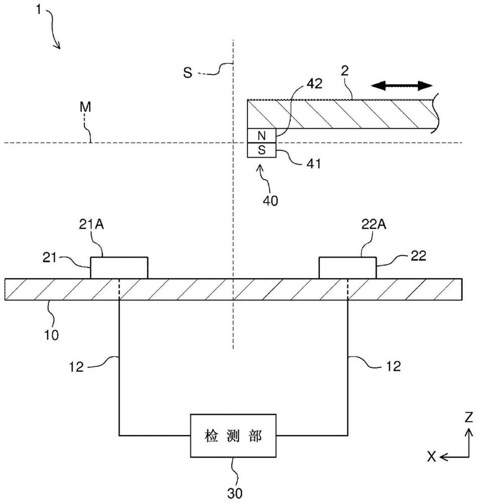
[0017] figure 1 It is a schematic diagram showing the configuration of the position detection device 1 according to the first embodiment of the present invention. like figure 1 As shown, the position detection device 1 of this embodiment includes: a fixed part 10; a pair of magnetic sensors 21, 22, which are fixed on the fixed part 10; a detection part 30, which is connected to the magnetic sensors 21, 22 via a signal line 12; And a magnet 40 mounted on the movable body 2 moved by detecting ...


PUM


Abstract

Provided is a position detection device that can stably detect a position with high detection precision over a long lifespan. A position detection device 2 is provided with a magnet 40 configured so as to move, together with a movable body 2, on a movement path M extending along the X-direction. The magnet 40 has different magnetic poles 41, 42 in the Z-direction. The position detection device 2 is provided with a pair of magnetic sensors 21, 22 that are separated by equal distances, in the Z-direction, from the movement path M, and that are disposed at equal distances from a reference line S extending in the Z-direction. The magnetic sensors 21, 22 have the same sensor characteristics. The position detection device 2 is provided with a detection unit 30 that is configured so as to detect that the magnet 40 is positioned on the reference line S when the outputs of the magnetic sensors 21, 22 match.

Description

technical field [0001] The invention relates to a position detection device, in particular to a position detection device for detecting the position of a movable body. Background technique [0002] For example, in a machine tool such as a machining center, it is necessary to detect the initial position of the tool in order to achieve precise machining. As a position detection device for detecting the position of a movable body moved by a detection target such as a tool, a device that mechanically switches electrical contacts corresponding to the movement of the movable body is known (for example, refer to Patent Document 1). [0003] However, such a conventional position detection device has a problem of short life due to degradation of contacts due to repeated mechanical switching. In addition, there is a problem that poor conduction between contacts occurs due to contamination of foreign matter or formation of an oxide film, or deterioration of detection accuracy occurs ...

Claims


Application Information

Patent Timeline
Patent Type & Authority Applications(China)
IPC IPC(8): G01D5/244G01D5/36
CPCG01D5/145G01D5/34
Inventor 吉冈崇元菅野隆行
Owner METROL CO LTD
Why Eureka
Try Eureka