High performance energy storage devices

a technology of energy storage and high-performance batteries, which is applied in the direction of battery, sustainable manufacturing/processing, cell components, etc., can solve the problems of lead-acid batteries failing prematurely, sulphate cannot be efficiently converted back to sponge, and the batteries used in these vehicles still suffer from a number of problems

Active Publication Date: 2007-05-10
COMMONWEALTH SCI & IND RES ORG
View PDF98 Cites 142 Cited by
  • Summary
  • Abstract
  • Description
  • Claims
  • Application Information

AI Technical Summary

Benefits of technology

[0035] This aspect of the invention can be applied equally to other hybrid battery types to avoid gasing.

Problems solved by technology

Whilst there have been many significant advances in the development of new batteries and power networks for vehicles relying at least partly on electric power, the batteries used in these vehicles still suffer from a number of problems.
This largely arises as a result of high current demands on the battery.
Under simulated HRPSOC duty, such as hybrid and mild hybrid electric vehicle operations, the lead-acid batteries fail prematurely mainly due to the progressive accumulation of lead sulphate on the surfaces of the negative plates.
This occurs because the lead sulphate cannot be converted efficiently back to sponge lead during charging either from the regenerative braking or from the engine.
Eventually, this layer of lead sulphate develops to such an extent that the effective surface area of the plate is reduced markedly, and the plate can no longer deliver the higher current demanded from the automobile.
This significantly reduces the potential life span of the battery.

Method used


Image

  • High performance energy storage devices
  • High performance energy storage devices
  • High performance energy storage devices

Examples


example 1

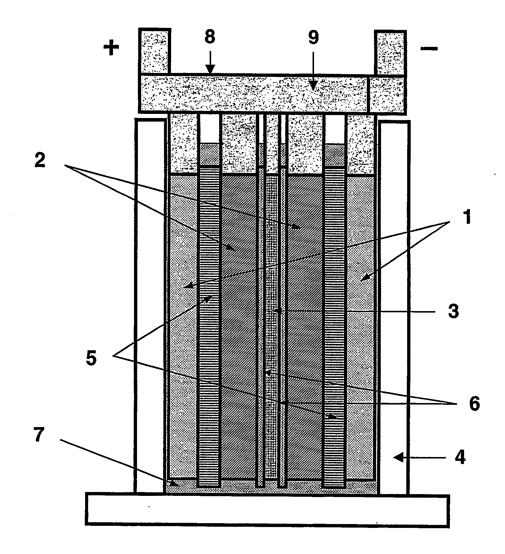
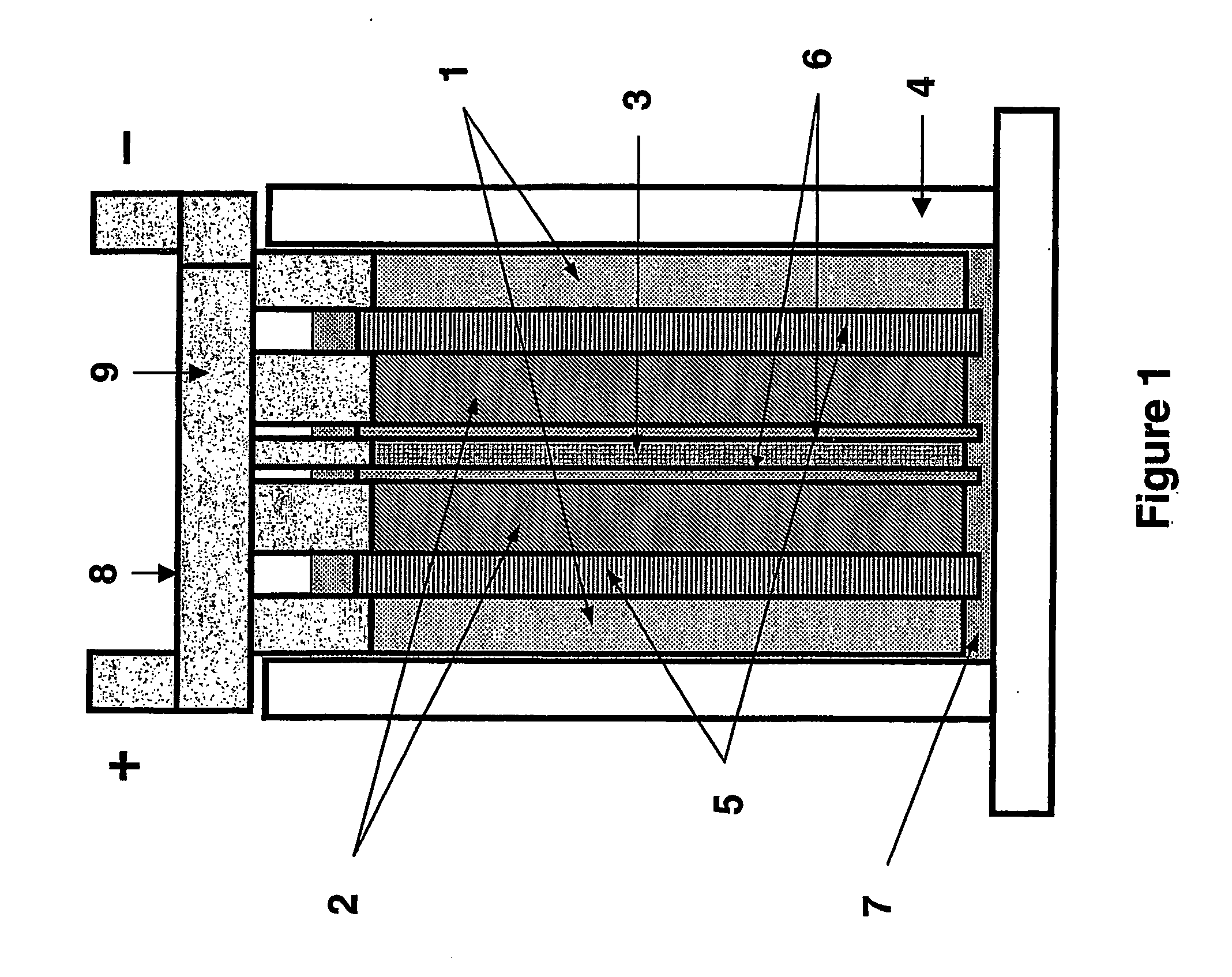
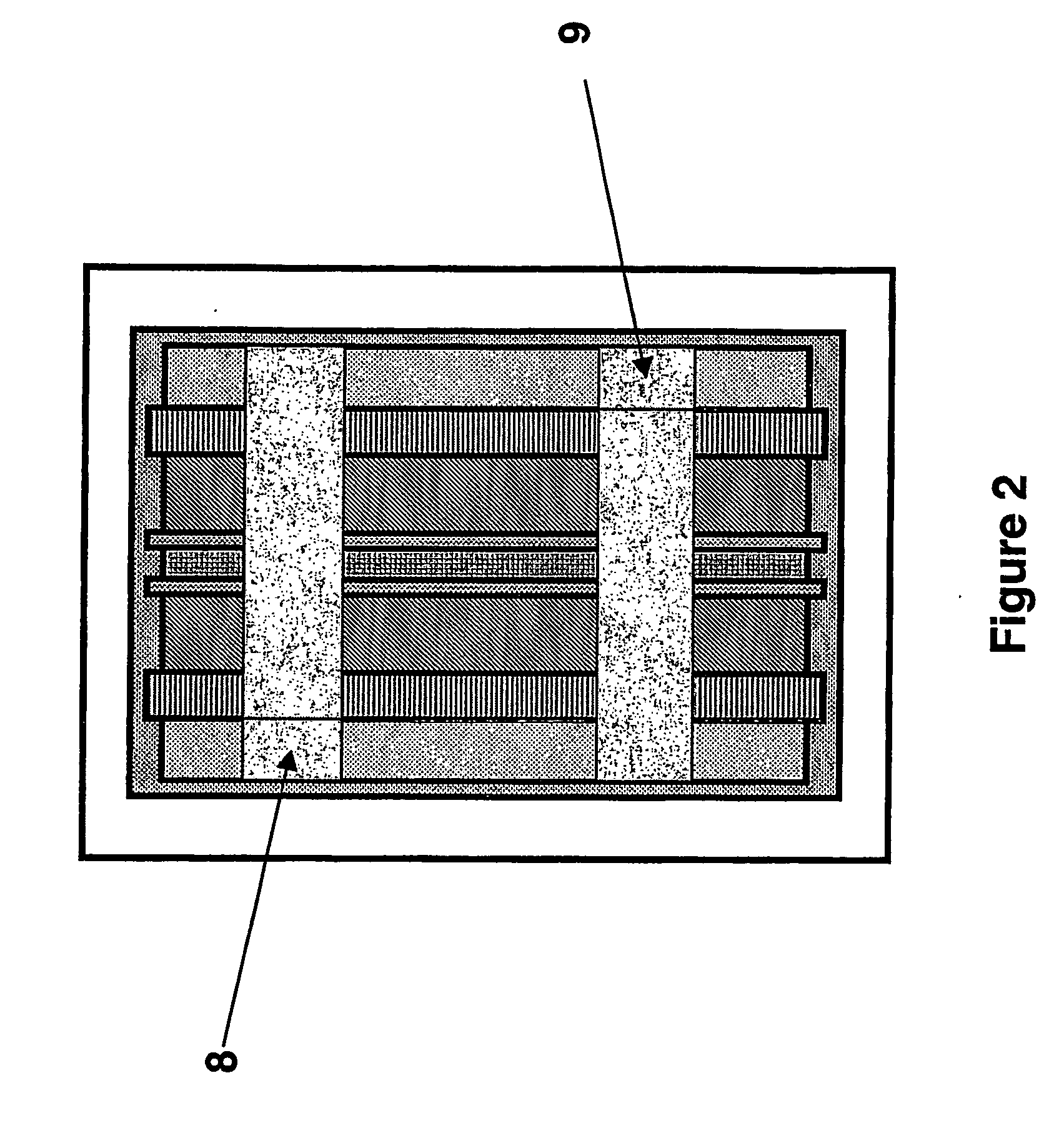
[0106] A lead-acid battery of one embodiment of the invention suitable for testing purposes was made in the arrangement as illustrated schematically in FIGS. 1 and 2.

[0107] Two sponge lead (negative plate) electrodes (1), two lead dioxide positive plate electrodes (2) and one high surface-area negative carbon electrode plate (3) were positioned in an alternating arrangement as illustrated in FIG. 1 in a battery case (4). The positive lead dioxide electrodes (2) and negative lead electrodes (1) were 40 millimetres wide by 68 millimetres high by 3.3 millimetres thick. The carbon electrode (3) was 40 millimetres wide by 68 millimetres high by 1.4 millimetres thick. The battery electrodes were of a standard configuration and composition for lead-acid batteries, and were made by the methods described in the detailed description above. The lead electrode formation techniques used in this example are more fully described in our copending application PCT / AU2003 / 001404, the entire contents ...

example 2

[0127] A variation on the battery of Example 1 is illustrated in FIGS. 5 and 6. For ease of comparison, the same numerals are used to refer to common features of the two batteries.

[0128] The embodiment of this Example comprises three lead dioxide positive plate electrodes (2) and two composite negative electrodes (16). The composite negative electrodes comprise a current collector or grid (17) with the lead-containing paste composition described above applied to one region (the face) thereof (18) and capacitor high surface-area carbon electrode material-containing paste applied to the opposite face (19). Formation of the electrode is conducted in the manner known in the art. In a variation on this embodiment that is simpler to manufacture, a lead based negative electrode is prepared with lead pasted by conventional dipping techniques to the main body section in lead paste material, followed by formation, and then the capacitor material is pasted to a region or regions of this lead ...

example 3

[0132] Further testing on the battery of Example 1 showed that improvements in electrolyte dry-out could be achieved by matching the hydrogen evolution rate of the carbon electrode (3) during battery charging to be similar to that of the lead negative electrode (1). This was achieved by replacing the carbon electrode of Example 1 with a modified carbon electrode (103) with 2.5 wt % PbO and 2.5 wt % ZnO, 65 wt % activated carbon, 20 wt % carbon black and binder (10 wt %) in the paste composition.

[0133] The hydrogen evolution rates for this electrode were tested and compared to the electrode used in Example 1, as well as the hydrogen evolution rates of the lead negative electrode of example 1. The results are shown in FIG. 7, in which curve 20 represents the carbon electrode hydrogen evolution rate, curve 21 represents the lead-acid negative plate hydrogen evolution rate, and the curve 22 represents the carbon plus additives electrode hydrogen evolution rate. The higher current densi...


PUM

PropertyMeasurementUnit
thicknessaaaaaaaaaa
thicknessaaaaaaaaaa
voltage windowaaaaaaaaaa

Abstract

A lead-acid battery comprising: at least one lead-based negative electrode; at least one lead dioxide-based positive electrode; at least one capacitor electrode; and electrolyte in contact with the electrodes; wherein a battery part is formed by the lead based negative electrode and the lead dioxide-based positive electrode; and an asymmetric capacitor part is formed by the capacitor electrode and one electrode selected from the lead based negative electrode and the lead-dioxide based positive electrode; and wherein all negative electrodes are connected to a negative busbar, and all positive electrodes are connected to a positive busbar. The capacitor electrode may be a capacitor negative electrode comprising carbon and an additive mixture selected from oxides, hydroxides or sulfates of lead, zinc, cadmium, silver and bismuth, or a capacitor negative electrode comprising carbon, red lead, antimony in oxide, hydroxide or sulfate form, and optionally other additives. The capacitor electrode may be used in asymmetric capacitors and batteries of other types.

Description

BACKGROUND OF THE INVENTION [0001] The present invention relates to high performance energy storage devices, including batteries such as lead-acid batteries and other battery types, as well as capacitor electrodes and asymmetric capacitors. [0002] There is growing demand for the development and introduction of vehicles that do not rely almost entirely on fossil fuels, to combat air pollution in urban environments and to reduce the global consumption of limited supplies of the fossil fuels. Such vehicles fall into three main classes: electric vehicles (EVs), hybrid electric vehicles (HEVs) and mild hybrid electric vehicles (also known as 42-volt powernet vehicles). [0003] Electric vehicles and hybrid electric vehicles may use a variety of different battery types, including lead-acid batteries. Mild hybrid electric vehicles may use mainly lead-acid batteries because of reduced cost. Hybrid and mild hybrid electric vehicles rely on a combination of an internal combustion engine and a b...

Claims


Application Information

Patent Timeline
Patent Type & Authority Applications(United States)
IPC IPC(8): H01M4/56H01M4/58H01M4/62H01M10/12H01M14/00H01M16/00H01M50/541
CPCH01M2/28H01M4/583H01M4/627H01M10/12H01M12/005H01M14/00Y02E60/13Y02E60/126Y02T10/7016H01G11/58H01G11/30Y02T10/7022H01M16/00Y02E60/10Y02T10/70H01M50/541Y02P70/50H01G11/04H01G11/38H01G11/46H01M12/00H01M10/52H01M4/14H01M2300/0011H01M2220/20
Inventor LAM, LAN TRIEUHAIGH, NIGEI PETERPHYLAND, CHRISTOPHER G.RANO, DAVID ANTHONY JAMES
Owner COMMONWEALTH SCI & IND RES ORG
Why Eureka
Try Eureka