Position detection system and position detection method
A detection system and position information technology, applied in diagnostic recording/measurement, in vivo radio detectors, medical science, etc., can solve the problems of capsule endoscopes being unable to move in the subject and poor observation ability
- Summary
- Abstract
- Description
- Claims
- Application Information
AI Technical Summary
Problems solved by technology
Method used
Image
Examples
Embodiment approach 1
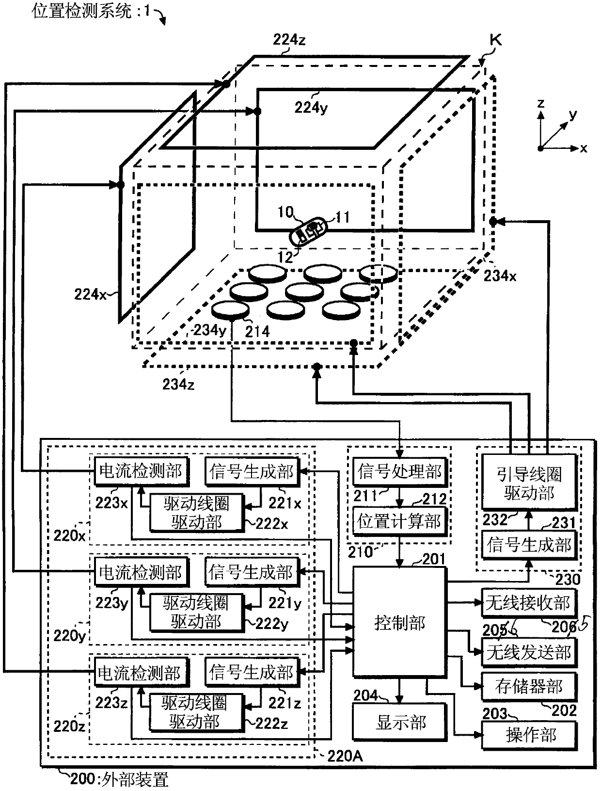
[0051] Next, the configuration and operation of the position detection magnetic guidance system 1 according to Embodiment 1 of the present invention will be described in detail using the drawings. In addition, this embodiment is for avoiding the need for the driving magnetic field generating device 220A (refer to figure 1 ) when the feedback control is performed, the error included in the position detection result derived becomes large, and thus, accurate position detection can be stably performed in the position detection magnetic guidance system 1 using the feedback control.
[0052] (structure)
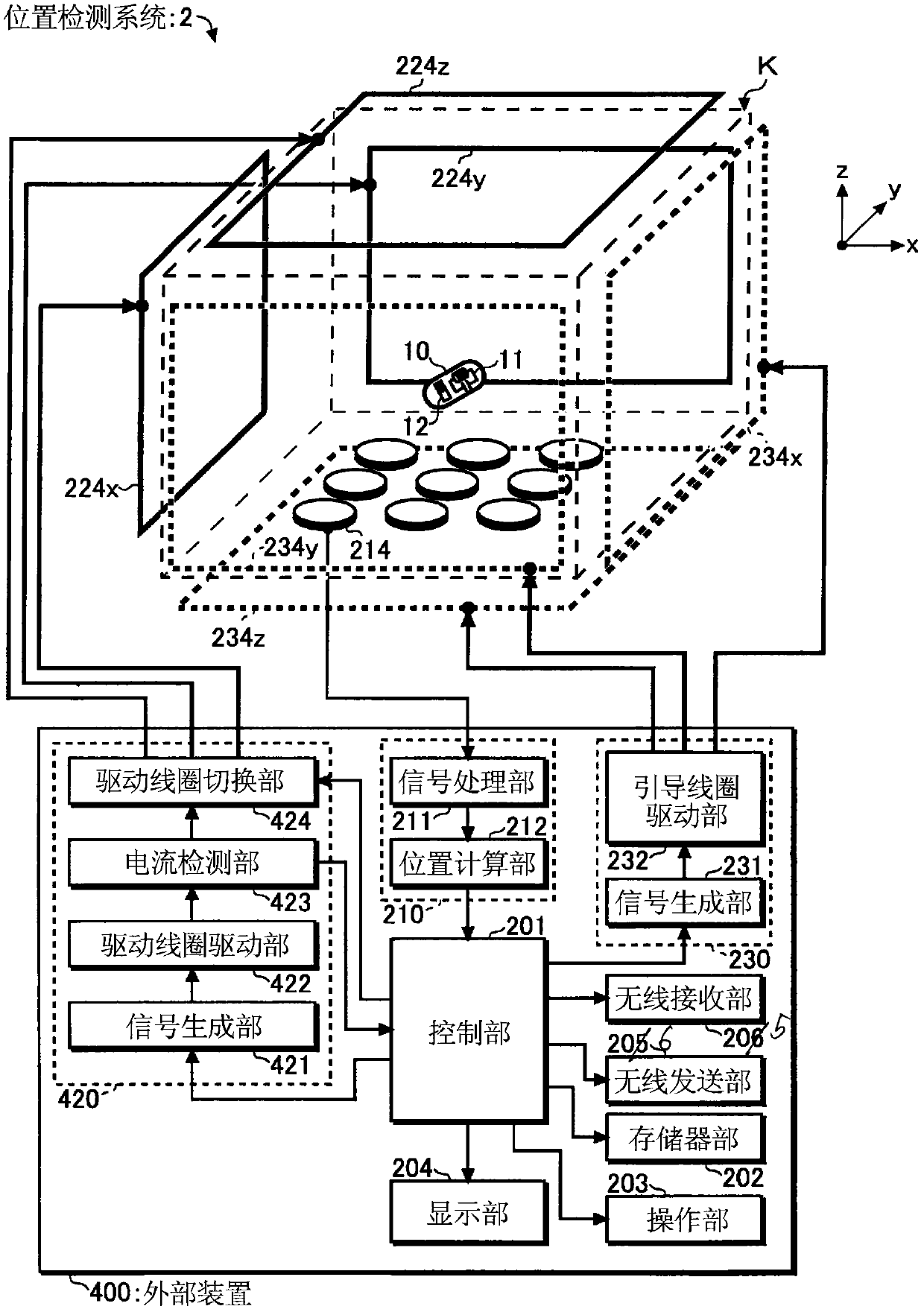
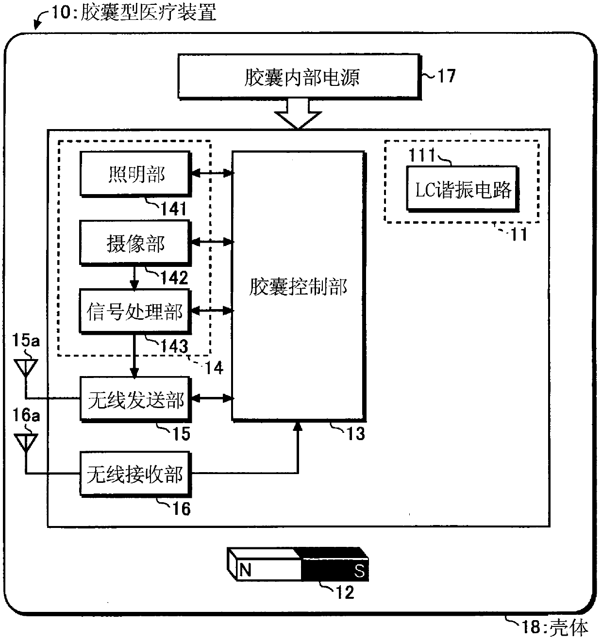
[0053] figure 1 It is a schematic diagram which shows the schematic structure of the position detection magnetic guidance system 1 of this embodiment. Such as figure 1 As shown, the position detection magnetic guidance system 1 is provided with a detection space K and an external device 200, the detection space K accommodates the subject to be introduced into the capsule medi...
Deformed example 1
[0113] In addition, in order to derive more accurate position and direction information, the position detection magnetic guidance system 1 of this embodiment is configured to take the average value of the detection signal (FFT data) output from the signal processing unit 211 of the position derivation unit 210, and calculate the position. The unit 212 calculates the position and direction information using the averaged detection signal (FFT data), or is configured to average the position and direction information output from the position derivation unit 210 in the control unit 201, etc., and various out of shape. Next, a case of averaging detection signals (FFT data) will be described as Modification 1 of the present embodiment. In addition, in the description below, the detection signal (FFT data) is simply referred to as FFT data.
[0114] Figure 8 It is a flowchart showing the general operation of the position calculation unit 212 in the first modification. Furthermore,...
Deformed example 2
[0122] In addition, for example, the number of data sets n in Modification 1 of the present embodiment can be reduced even when position detection is performed stably. This is because if each FFT data (or position and direction information) is correct, correct position and direction information can be acquired even without averaging a larger number of FFT data (or position and direction information).
[0123] Also, for example, the number n of data sets can be increased even when the position detection is unstable. This is because the accuracy of the derived position and orientation information is improved by averaging more FFT data (or position and orientation information).
[0124] In addition, the state where position detection is performed stably refers to a state where the absolute value of the difference between the previous amplitude value and the new amplitude value is equal to or less than the difference reference value 202d continues for a long period of time. In ad...
PUM
 Abstract
Description
Claims
Application Information
 - R&D
- Intellectual Property
- Life Sciences
- Materials
- Tech Scout
- Unparalleled Data Quality
- Higher Quality Content
- 60% Fewer Hallucinations
Browse by: Latest US Patents, China's latest patents, Technical Efficacy Thesaurus, Application Domain, Technology Topic, Popular Technical Reports.
© 2025 PatSnap. All rights reserved.Legal|Privacy policy|Modern Slavery Act Transparency Statement|Sitemap|About US| Contact US: help@patsnap.com


