Hermetically sealed rush adjuster
一种气门间隙、调节器的技术,应用在机器/发动机、阀装置、机械设备等方向,能够解决损害气门间隙调节器功能等问题
- Summary
- Abstract
- Description
- Claims
- Application Information
AI Technical Summary
Problems solved by technology
Method used
Image

Examples
Embodiment 1
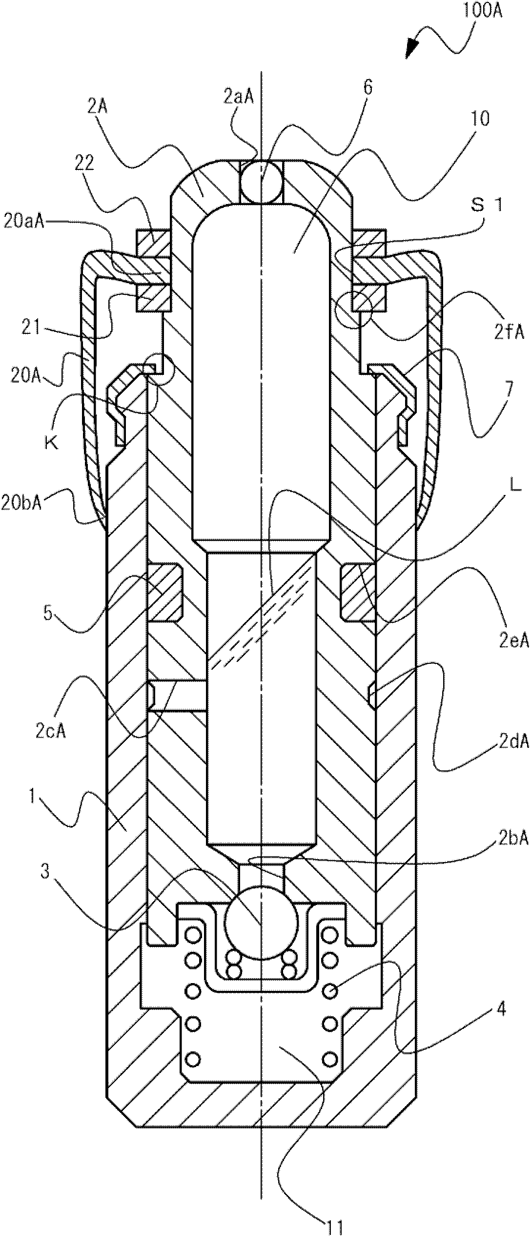
[0024] figure 1 It is a diagram schematically showing a sealed lash adjuster (hereinafter, also simply referred to as a lash adjuster) 100A of the present embodiment. The lash adjuster 100A has a main body 1 , a plunger 2A, a check valve 3 , a plunger spring 4 , a first seal member (first seal mechanism) 5 , a ball plug 6 , and a cap holder 7 as basic structures.
[0025] The main body 1 is a bottomed cylindrical member, and a plunger 2A is slidably inserted in the cylinder in a direction parallel to the central axis. At the front end portion of the main body 1, a cap holder 7 for restricting protrusion of the plunger 2A is arranged. The cap holder 7 functions as a stopper for the plunger 2 , and does not have a function of sealing liquid that may enter from the outside. The plunger 2A is a columnar member and has a storage chamber 10 formed therein. In addition, the storage chamber 10 may be formed in an appropriate shape. An injection hole 2aA for injecting oil (liquid) ...
Embodiment 2
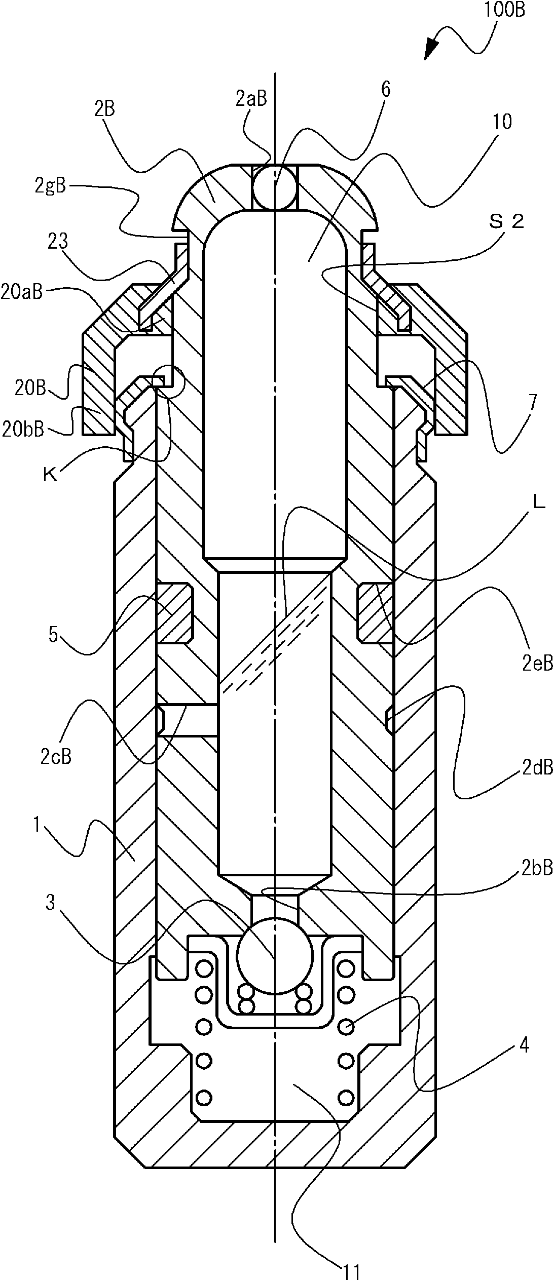
[0035] figure 2 It is a figure schematically showing the structure of the lash adjuster 100B of this embodiment. The lash adjuster 100B has the same basic structure as the lash adjuster 100A shown in the first embodiment except that the plunger 2A is changed to the plunger 2B. On the other hand, the lash adjuster 100B has a second sealing member 20B and its associated structures instead of the second sealing member 20A and its accompanying structures (first and second covers 21, 22) as parts other than the basic structure. It differs from the lash adjuster 100A in terms of an accompanying structure (holder 23 ).
[0036] Also in this embodiment, the second sealing member 20B is formed and arranged to seal the exposed portion of the plunger 2B and cover the gap K. As shown in FIG. On the other hand, in this regard, the second sealing member 20B is specifically formed and arranged as follows in the present embodiment. In addition, in this embodiment, the second sealing membe...
Embodiment 3
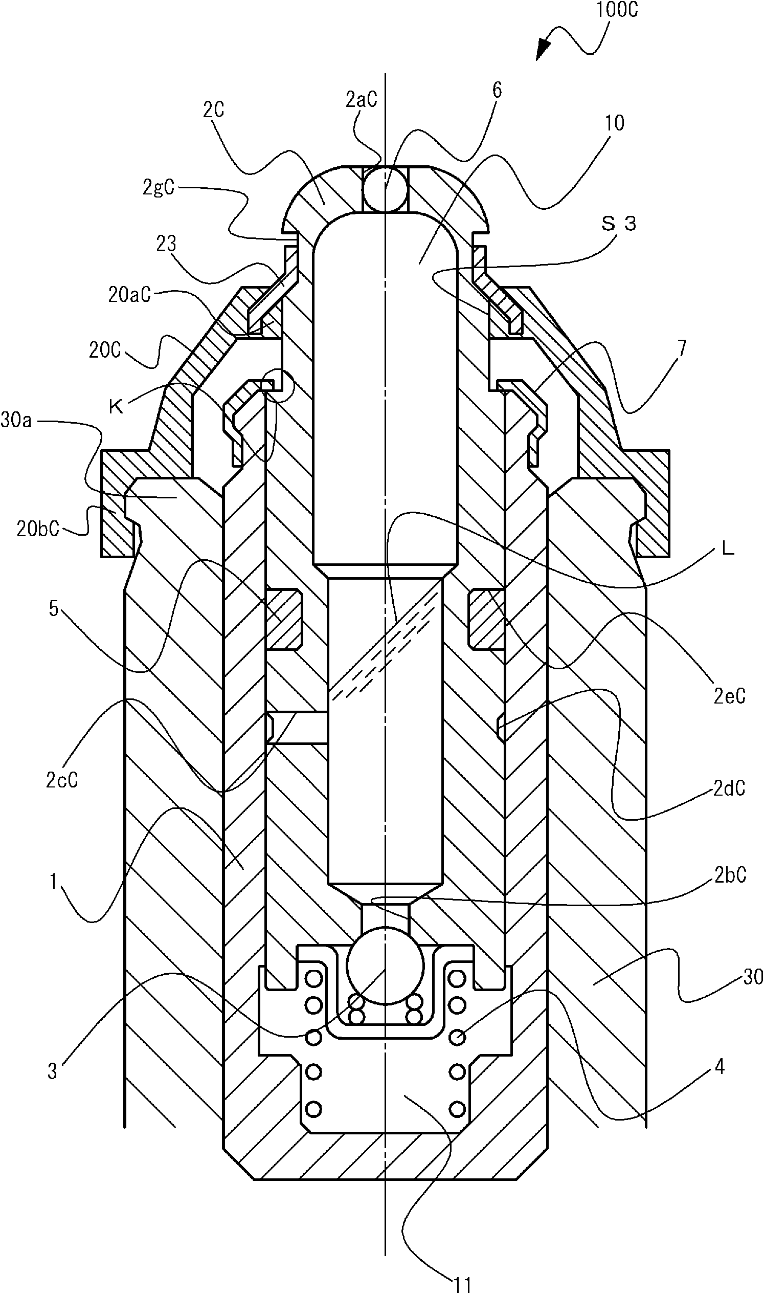
[0041] image 3 It is a diagram schematically showing the structure of a lash adjuster 100C of this embodiment. The lash adjuster 100C has the same basic structure as the lash adjuster 100A shown in the first embodiment except that the plunger 2A is changed to the plunger 2C. In addition, the plunger 2C is the same as the plunger 2B shown in Example 2. On the other hand, the lash adjuster 100C has a second sealing member 20C and its accompanying structure (holder 23 ) instead of the second sealing member 20A and its accompanying structure as a part other than the basic structure. Above, it is different from the lash adjuster 100A.
[0042] Also in this embodiment, the second sealing member 20C is formed and arranged to seal the exposed portion of the plunger 2C and cover the gap K at the opening end portion of the main body 1 . On the other hand, in this regard, the second sealing member 20C is specifically formed and arranged as follows in the present embodiment. In addit...
PUM
 Abstract
Description
Claims
Application Information
 - R&D
- Intellectual Property
- Life Sciences
- Materials
- Tech Scout
- Unparalleled Data Quality
- Higher Quality Content
- 60% Fewer Hallucinations
Browse by: Latest US Patents, China's latest patents, Technical Efficacy Thesaurus, Application Domain, Technology Topic, Popular Technical Reports.
© 2025 PatSnap. All rights reserved.Legal|Privacy policy|Modern Slavery Act Transparency Statement|Sitemap|About US| Contact US: help@patsnap.com