Hermetically sealed rush adjuster
A valve clearance and adjuster technology, which is applied in the directions of machines/engines, valve devices, mechanical equipment, etc., can solve problems such as damage to the valve clearance adjuster function, and achieve high restraint effect and restraint wear effect.
- Summary
- Abstract
- Description
- Claims
- Application Information
AI Technical Summary
Problems solved by technology
Method used
Image

Examples
Embodiment 1
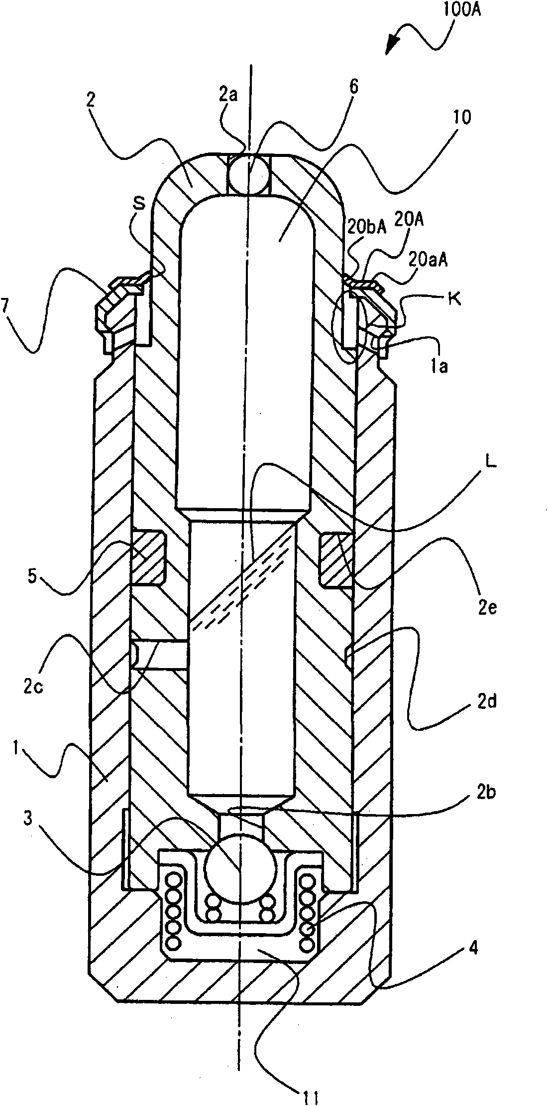
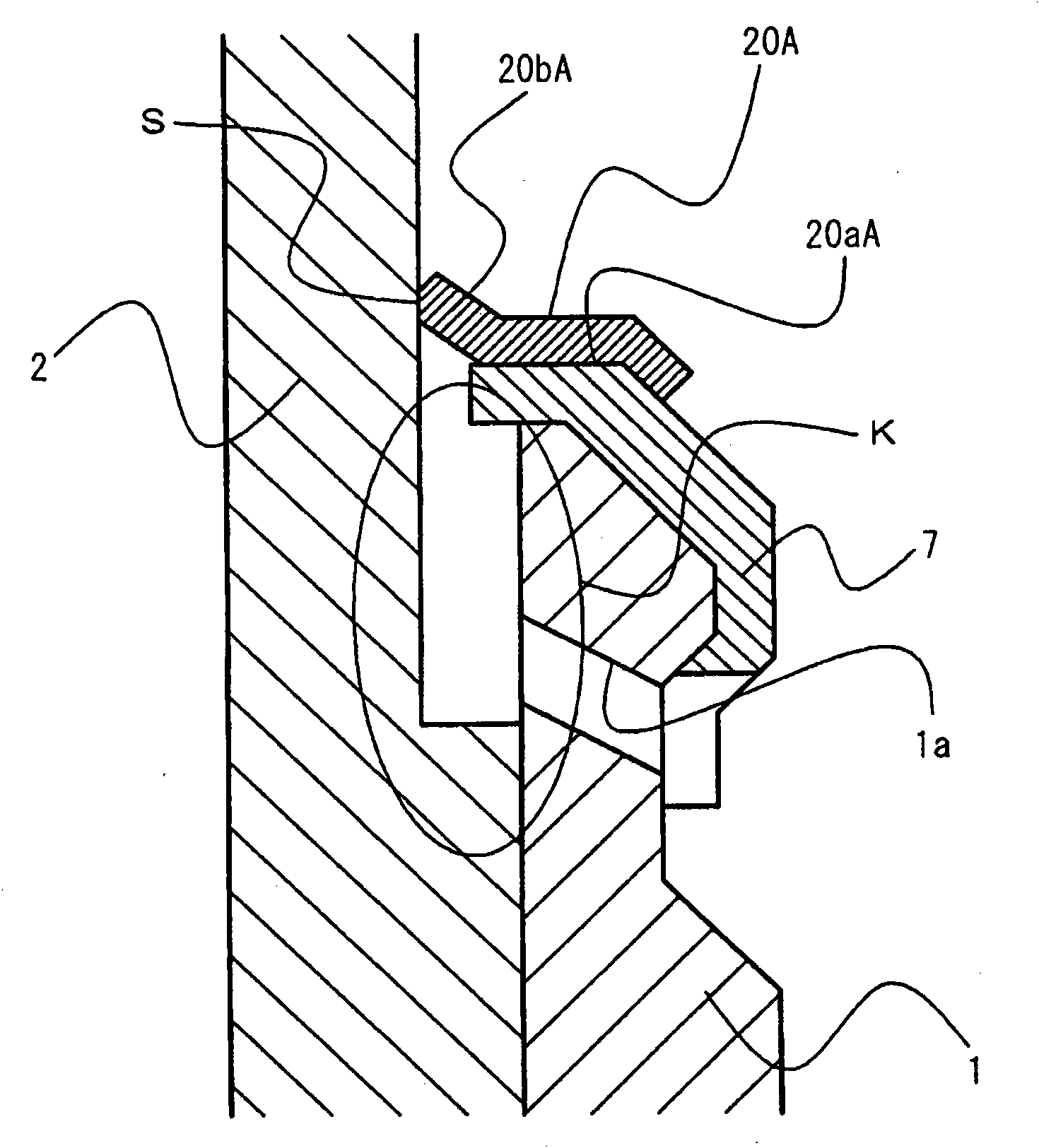
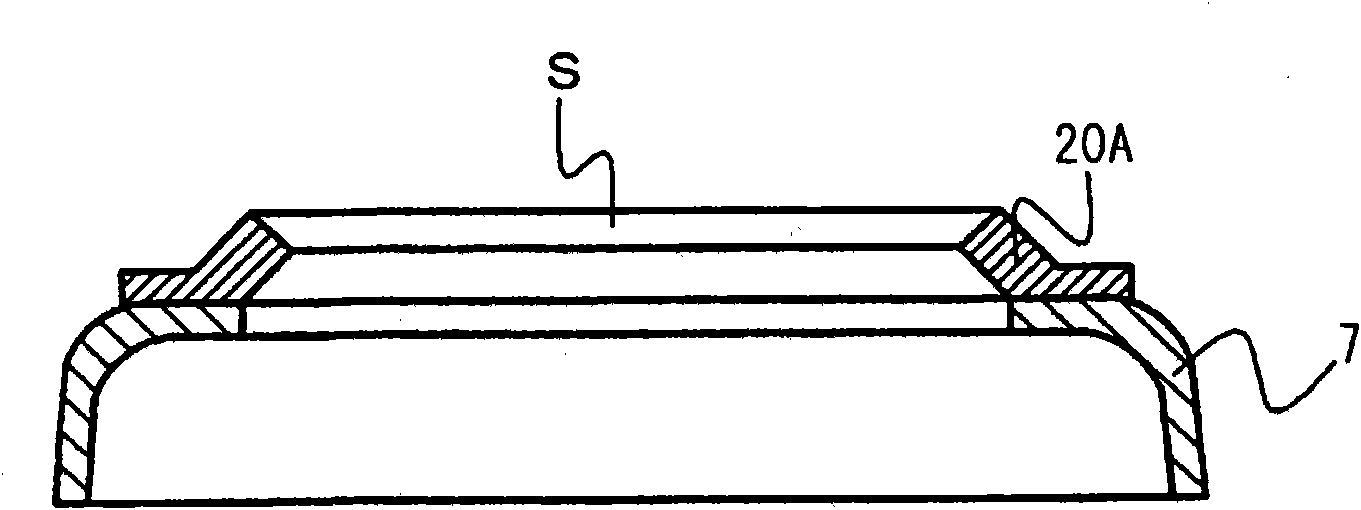
[0028] figure 1 It is a diagram schematically showing the structure of a sealed lash adjuster (hereinafter also simply referred to as a lash adjuster) 100A of the present embodiment. The lash adjuster 100A has a main body 1 , a plunger 2 , a check valve 3 , a plunger spring 4 , a first sealing member (first sealing device 5 ), a ball plunger 6 , and a cap holder 7 as a basic structure.
[0029]The main body 1 is a cylindrical member with a bottom, and the plunger 2 is slidably inserted in the cylinder in a direction parallel to the central axis. A cap holder 7 for restricting protrusion of the plunger 2 is arranged at the front end portion of the main body 1 . The cap holder 7 is configured to function as a fall-off prevention member for the plunger 2 and has no function of sealing liquid that may enter from the outside. The plunger 2 is a columnar member and forms a storage chamber 10 inside. The reservoir 10 may be formed in an appropriate shape. An injection hole 2 a fo...
Embodiment 2
[0046] Figure 7 It is a diagram schematically showing a part of the structure of the lash adjuster 100B of this embodiment with the second seal member 20B as the main part. The lash adjuster 100B has the same structure as the lash adjuster 100A except that a second sealing member 20B is provided instead of the cover holder 7 and the second sealing member 20A. The second seal member 20B is made of rubber and functions not only as a seal but also as a plunger retainer. The material of the second sealing member 20B is not limited to rubber, and appropriate materials such as other elastic materials may be used. The second sealing member 20B slidably seals the exposed portion of the plunger 2 with the other end portion 20bB formed in a rim shape. In addition, the second seal member 20B is disposed so as to cover the gap K in a state where the one end portion 20aB is directly tightly fixed to the main body 1 by tightening the rubber itself.
[0047] Even if the second sealing de...
Embodiment 3
[0049] Figure 8It is a diagram schematically showing a part of the structure of the lash adjuster 100C of the present embodiment with the communication hole 1 a as the main part. The lash adjuster 100C is the same as the lash adjuster 100B except that the communication hole 1 a is formed as follows. Furthermore, the communication hole 1 a of the lash adjuster 100A may also be formed as shown below. In this embodiment, the communication hole 1a is configured so that the lowest point P of the communication hole 1a is higher than the opening end position F of the assembly hole 30a formed in the cylinder head 30 in the direction Y in which the central axis of the main body 1 extends. way to form. However, the assembly hole 30 a is not limited to being formed in the cylinder head 30 , and may be formed in another component for assembling the lash adjuster 100C.
[0050] In this way, the engine oil intruded into the gap K can be better discharged from the communication hole 1 a ...
PUM
 Abstract
Description
Claims
Application Information
 - R&D
- Intellectual Property
- Life Sciences
- Materials
- Tech Scout
- Unparalleled Data Quality
- Higher Quality Content
- 60% Fewer Hallucinations
Browse by: Latest US Patents, China's latest patents, Technical Efficacy Thesaurus, Application Domain, Technology Topic, Popular Technical Reports.
© 2025 PatSnap. All rights reserved.Legal|Privacy policy|Modern Slavery Act Transparency Statement|Sitemap|About US| Contact US: help@patsnap.com