
Liquid discharging apparatus and control method of liquid discharging apparatus

一种液体、设备的技术,应用在液体喷射设备以及液体喷射设备的控制领域,能够解决误排出墨水、波形设计自由度下降、弯液面振动放大等问题

Active Publication Date: 2011-09-21
SEIKO EPSON CORP
View PDF7 Cites 6 Cited by
  • Summary
  • Abstract
  • Description
  • Claims
  • Application Information

AI Technical Summary

Problems solved by technology

Therefore, it is conceivable to provide the pressure generating element with a micro-vibration waveform that only increases the amount of voltage change. The residual vibration of the liquid surface is added to the pressure fluctuation caused by the discharge element that occurs later, and the vibration of the meniscus is amplified, which may cause ink to be discharged from the nozzle opening by mistake.
In addition, in order to prevent the above-mentioned erroneous discharge, it is also conceivable to extend the time width of the discharge element that supplies the micro-vibration pulse, but since the overall waveform length of the micro-vibration pulse becomes longer, there is a possibility that high-frequency driving cannot be performed or the degree of freedom in waveform design is reduced. The problem

Method used


Image

  • Liquid discharging apparatus and control method of liquid discharging apparatus
  • Liquid discharging apparatus and control method of liquid discharging apparatus
  • Liquid discharging apparatus and control method of liquid discharging apparatus

Examples


Embodiment Construction

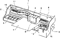
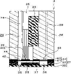
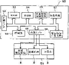
[0021] Hereinafter, preferred modes for carrying out the present invention will be described with reference to the drawings and the like. In the embodiments described below, various limitations are made as preferred specific examples of the present invention, but the scope of the present invention is not limited to these forms unless the present invention is particularly limited in the following description. In addition, in this embodiment, an inkjet type recording apparatus (hereinafter referred to as "printer") is taken as an example of a liquid ejection device, and an inkjet type recording head (hereinafter referred to as "printer") is taken as an example of a liquid ejection head. as "recording head") as an example.

[0022] figure 1 It is a perspective view for explaining the configuration of the printer 1 . This printer 1 includes, inside a housing 2, a carriage 5 on which a recording head 3, which is a type of liquid ejection head, is mounted, and an ink cartridge 4 s...


PUM


Abstract

The invention provides a liquid discharging apparatus and a control method of liquid discharging apparatus. A contraction portion (3) of a vibration pulse (DPC) includes a first contraction element (p31) which occurs subsequent to an expansion portion (p1), a contraction maintaining element (p32) which follows the first contraction element (p31), and a second contraction element (p33) which follows the contraction maintaining element (p32), and when a time from a start point time of the expansion portion (p1) to an end point time of the expansion portion (p1) is set as t1, a time from the end point time of the expansion portion (p1) to a start point time of the contraction portion (p3) is set as t2, and a natural vibration period of ink in an ink flow path including a pressure chamber is set as Tc, the start point time (t1+t2) of the contraction portion is set to be in the range of any one of the following expressions (1) and (2): (t1+t2)<t1 / 2+3Tc / 8 (1), (t1+t2)>t1 / 2+5Tc / 8 (2)..

Description

[0001] This application claims priority from Japanese Patent Application No. 2010-42598 filed on February 26, 2010, which is hereby incorporated by reference. technical field [0002] The present invention relates to a liquid ejection device such as an inkjet printer and a control method for the liquid ejection device. Background technique [0003] As a liquid ejection device, there is a device configured to generate a drive signal including a drive pulse (discharge pulse) by applying (supplying) the generated drive pulse to a pressure generating element (for example, a piezoelectric vibrator or a heating element, etc.). The pressure generating element is driven to cause pressure fluctuations in the liquid in the pressure generating chamber (a type of pressure chamber), and the pressure fluctuation is used to discharge the liquid from a nozzle opening communicating with the pressure generating chamber. And, in the liquid ejecting apparatus configured to generate a plurality ...

Claims


Application Information

Patent Timeline
Patent Type & Authority Applications(China)
IPC IPC(8): B41J2/045B41J29/393
CPCB41J2/04573B41J2/14274B41J2/04581B41J2/04588
Inventor 米久保直树
Owner SEIKO EPSON CORP
Learn More