
Assist handle spring design for constant return velocity

一种扶手、主弹簧的技术,应用在扶手组件领域,能够解决扭簧没有呈现扭矩曲线等问题

Active Publication Date: 2011-09-21
GM GLOBAL TECH OPERATIONS LLC
View PDF5 Cites 3 Cited by
  • Summary
  • Abstract
  • Description
  • Claims
  • Application Information

AI Technical Summary

Problems solved by technology

However, torsion springs do not exhibit a uniform torque curve

Method used


Image

  • Assist handle spring design for constant return velocity
  • Assist handle spring design for constant return velocity
  • Assist handle spring design for constant return velocity

Examples


Embodiment Construction

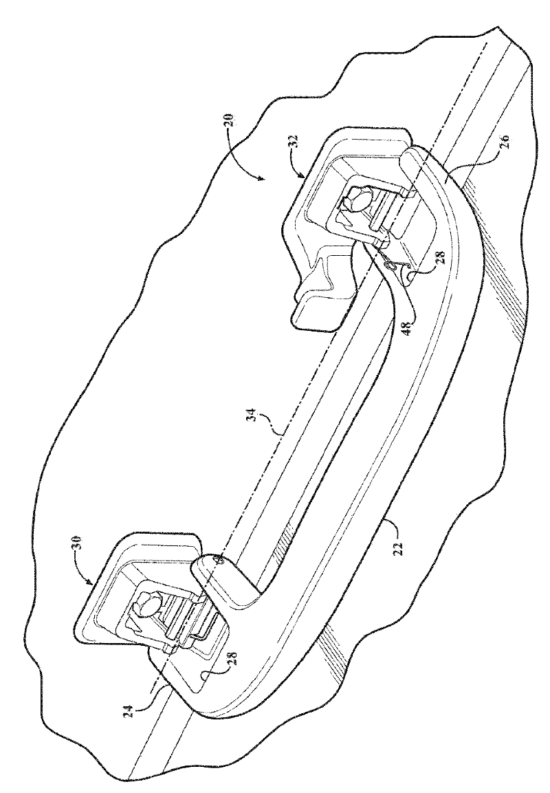
[0052] Referring to the Figures, wherein like numerals indicate like parts throughout the views, an armrest assembly is shown generally at 20 . The armrest assembly 20 is disposed in the interior of the passenger compartment of the automobile. A passenger can grasp the armrest assembly 20 to facilitate entry into and / or exit from the vehicle cabin.

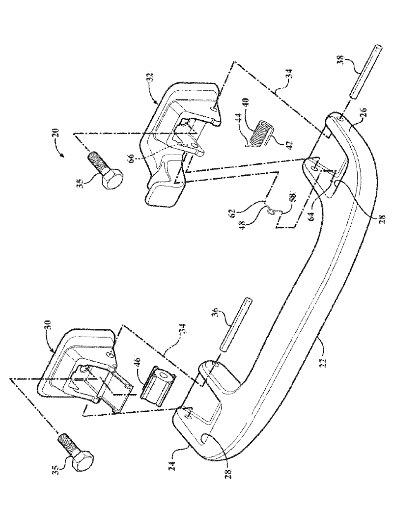
[0053] refer to figure 1 and 2 , the armrest assembly 20 has a main body 22 . The body 22 has a first end 24 and a second end 26 . The first end portion 24 and the second end portion 26 are disposed at opposite ends of the body 22 along the longitudinal axis of the body 22 . The body 22, including the first end 24 and the second end 26, may be configured in any suitable manner to suit the vehicle and any ergonomic requirements. As shown, the body 22 has a generally rounded rectangular cross-section with a first end 24 and a second end 26 extending laterally from the body 22 in a coplanar fashion. As shown, both the first end...


PUM


Abstract

The invention relates to assist handle spring design for constant return velocity. An assist handle assembly for a vehicle includes a body and at least a first hinge assembly rotatably coupled to the body. A primary spring interconnects the body and the first hinge assembly and biases the body from an open position into a stowed position. A secondary spring interconnects the body and the first hinge assembly, and biases against the primary spring when the body is between the open position and an intermediate position to resist rotation of the body into the stowed position, and biases with theprimary spring when the body is between the intermediate position and the stowed position to assist rotation of the body into the stowed position.

Description

technical field [0001] The present invention generally relates to an armrest assembly for assisting a passenger in entering and / or exiting the passenger compartment of a motor vehicle. Background technique [0002] Some automobiles have armrests arranged inside the passenger compartment of the automobile. Passengers can grasp the armrest to assist in entering and / or exiting from the vehicle cabin. [0003] Some armrest assemblies include spring powered retractable handles. The handle automatically retracts out of the way to the stowed position when not in use. In use, a passenger grabs the handle and pulls the handle to the open position, at which point the passenger can leverage on the armrest to aid entry and / or exit. A spring automatically biases the handle back to the stowed position immediately after the handle is released. The armrest may include a damper to slow the return of the handle to the stowed position, thereby preventing the handle from "snapping" back to ...

Claims


Application Information

Patent Timeline
Patent Type & Authority Applications(China)
IPC IPC(8): B60N3/02
CPCB60N3/023B60N3/026
Inventor B.K.巴特尼克
Owner GM GLOBAL TECH OPERATIONS LLC
Learn More