Supercharge Your Innovation With Domain-Expert AI Agents!

Pod-type vortex-induced vibration suppression device

A vortex-induced vibration and suppression device technology, applied in the direction of fluid flow, mechanical equipment, etc., can solve the problems of reducing production costs, weakening hydrodynamic loads, etc., and achieve the effects of reducing production costs, weakening hydrodynamic loads, and solving vortex-induced vibrations

Inactive Publication Date: 2013-10-30
CHINA NAT OFFSHORE OIL CORP +2
View PDF4 Cites 0 Cited by
  • Summary
  • Abstract
  • Description
  • Claims
  • Application Information

AI Technical Summary

Problems solved by technology

[0004] The main purpose of the present invention is to overcome the above-mentioned shortcomings in the prior art, and provide a pod-type vortex-induced vibration suppression device, which can not only adapt to incoming flows in different directions, but also weaken the hydrodynamic load on the structure to a certain extent , so as to solve the problem of vortex-induced vibration of the blunt body immersed in the fluid; at the same time, reduce the production cost

Method used


Image

  • Pod-type vortex-induced vibration suppression device
  • Pod-type vortex-induced vibration suppression device
  • Pod-type vortex-induced vibration suppression device

Examples


Embodiment Construction

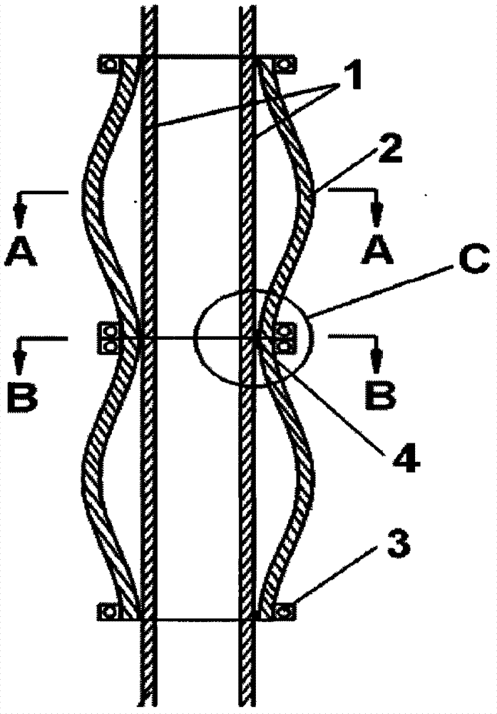
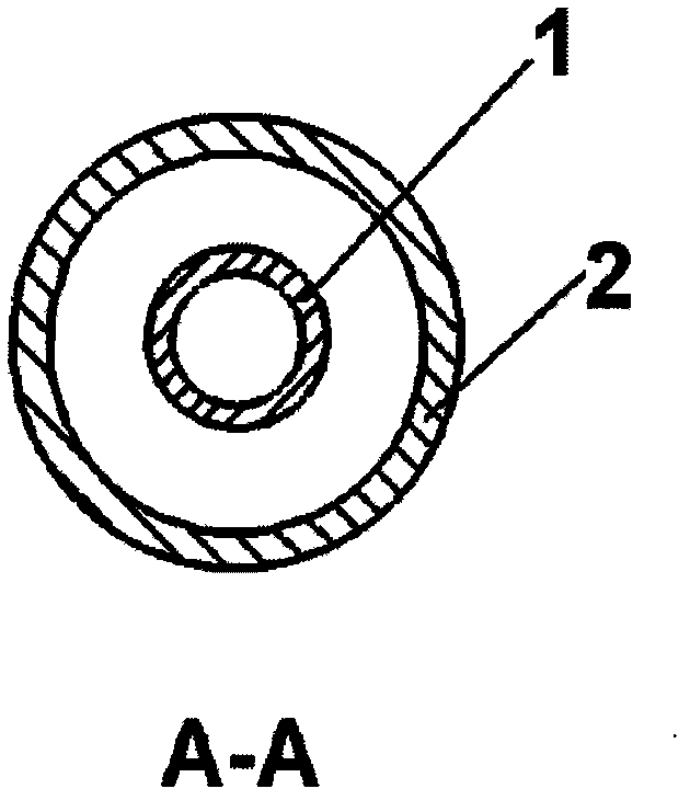
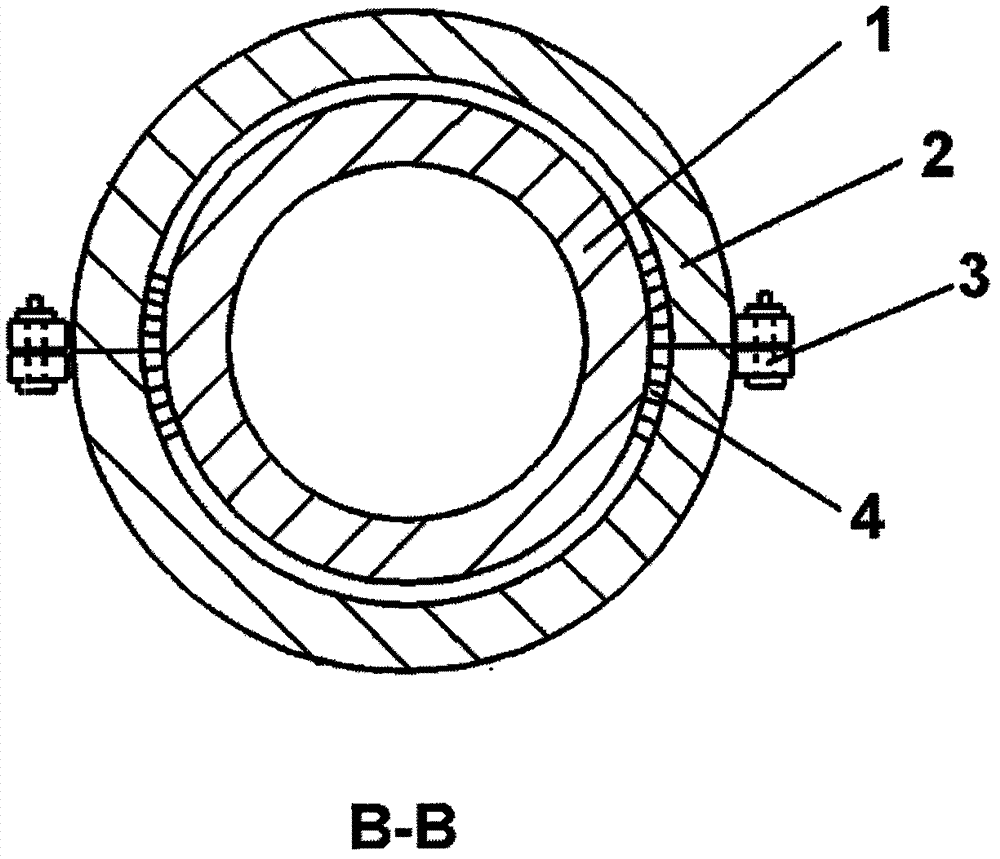
[0020] Such as Figure 1-Figure 4 As shown, the present invention includes: several sections of housing 2 with a circular cross-section, the housing 2 is fastened on the outer thin layer of the pipe 1 as the middle body part, and along the axial direction of the pipe 1, the thin layer is a simple harmonic type Change, the cross section is circular. The smallest diameter is called the trough (the diameter is slightly larger than the diameter of the pipe 1), and the largest diameter is called the peak; the radial difference between the smallest diameter position and the largest diameter position is called the wave height, and the axis between two adjacent smallest diameter positions The distance to the wavelength is the wavelength; the ratio of the wave height to the wavelength is called the wave steepness intensity, and the ratio of the wave height to the wavelength of the simple harmonic is greater than 0.05.

[0021] The outer surface of the shell 2 along the span direction ...


PUM


Abstract

A pod-type vortex-induced vibration suppression device includes several sections of shells with circular cross-sections. half, and through the snap-fit ​​devices at both ends of each segment, they are butted into a whole suppression cover. The invention can not only adapt to incoming flows in different directions, but also weaken the hydrodynamic load on the structure to a certain extent, thereby solving the problem of vortex-induced vibration on blunt bodies immersed in the fluid; at the same time, the production cost is reduced.

Description

technical field [0001] The invention relates to a vibration suppression device, in particular to a pod-type vortex-induced vibration suppression device for reducing the hydrodynamic load on blunt bodies exposed to fluids and weakening and suppressing structural vibration caused by vortex shedding. Background technique [0002] When the fluid bypasses the blunt body structure, due to physical reasons such as fluid viscosity, alternating shedding vortices appear at the rear of the structure; this vortex motion causes the structure to be subjected to alternately changing pulsating lateral forces (called lift), and the fluid’s impact on the blunt body. Flow direction force exerted by the structure, i.e. the structure is resisted. After the structure is resisted, it will displace along the flow direction, which will cause the end buildings linked to the column structure, such as platforms, to drift within a certain range; and the lift force on the structure will be due to its dir...

Claims


Application Information

Patent Timeline
Patent Type & Authority Patents(China)
IPC IPC(8): F15D1/00
Inventor 吴应湘刘培林钟兴福潘晓东林黎明张艳芳何杨郝双户
Owner CHINA NAT OFFSHORE OIL CORP
Features
  • R&D
  • Intellectual Property
  • Life Sciences
  • Materials
  • Tech Scout
  • Unparalleled Data Quality
  • Higher Quality Content
  • 60% Fewer Hallucinations
Learn More