CVT

A technology of continuously variable transmission and rotating elements, applied in the direction of transmission, friction transmission, belt/chain/gear, etc., can solve the problem of reducing torque transmission efficiency and achieve the effect of suppressing the reduction of transmission efficiency

Inactive Publication Date: 2011-11-30
TOYOTA JIDOSHA KK
View PDF6 Cites 4 Cited by
  • Summary
  • Abstract
  • Description
  • Claims
  • Application Information

AI Technical Summary

Problems solved by technology

This deviation is related to the deviation between the rotation direction of the rotating member and the rotation direction of the third rotation el

Method used


Image

  • CVT
  • CVT
  • CVT

Examples


Embodiment

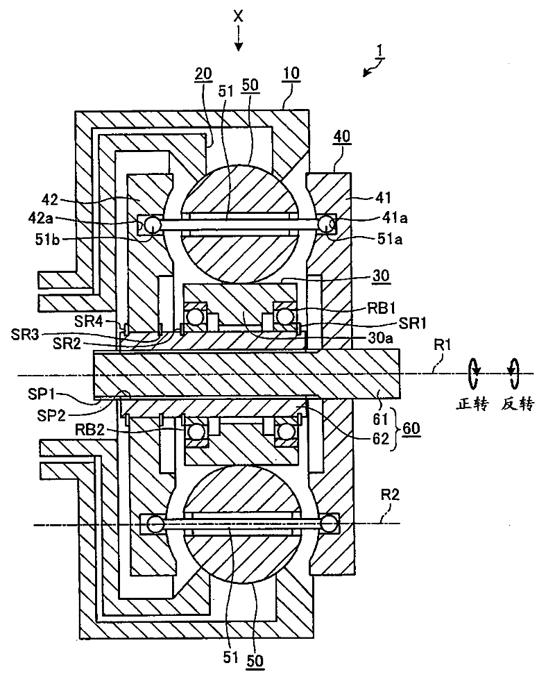
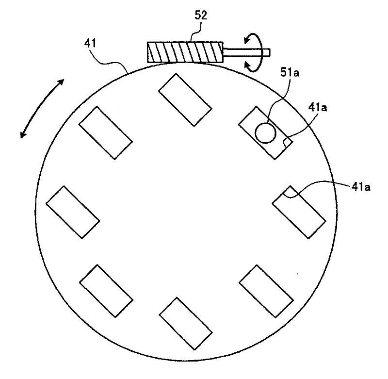
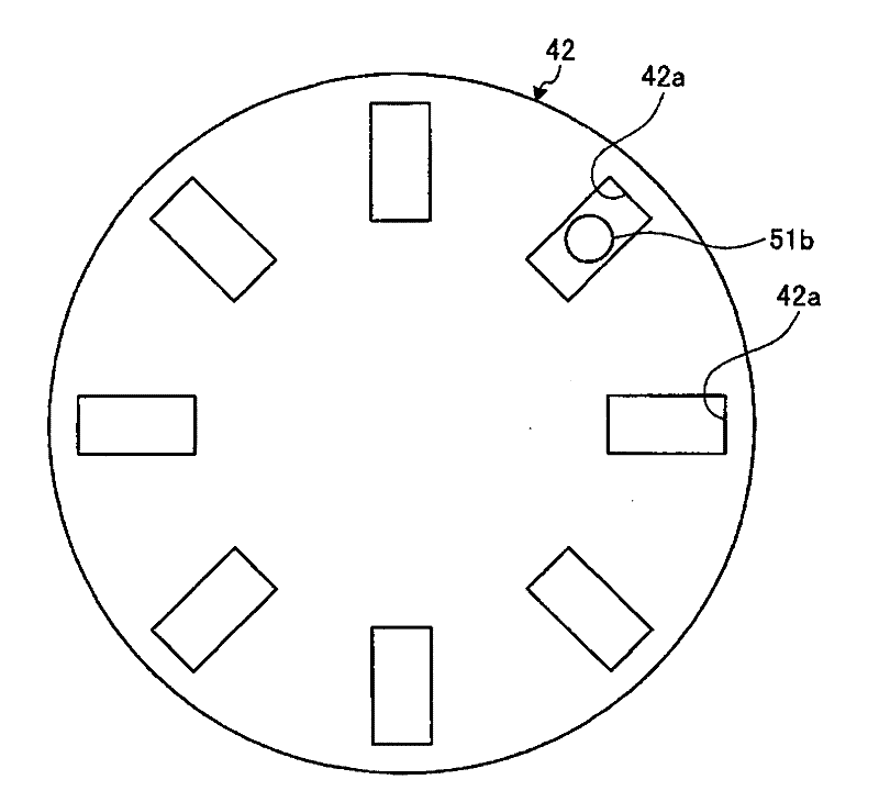
[0027] based on Figure 1 to Figure 7 Embodiments of the continuously variable transmission according to the present invention will be described.

[0028] Initially, use figure 1 An example of the continuously variable transmission of this embodiment will be described. figure 1 Symbol 1 in represents the continuously variable transmission of this embodiment.

[0029] The continuously variable transmission mechanism constituting the main part of the continuously variable transmission 1 is a so-called traction planetary mechanism. The rotating elements 10, 20, 30, 40 have a common first rotating center axis R1 and can perform relative rotation with each other; a plurality of fifth rotating elements 50, the plurality of fifth rotating elements 50 have a Another second rotational central axis R2 parallel to the central axis R1 at a reference position described later; In this continuously variable transmission 1 , the gear ratio between input and output is changed by tilting th...


PUM


Abstract

Provided is a continuously variable transmission provided with first and second rotating members (10, 20) which have common first rotation central axes (R1); planetary balls (50) which are rotatably supported by support shafts (51) having second rotation central axes (R2) that are other than the first rotation central axes (R1), which are held by first rotating members (10) and second rotating members (20) in such a way as to be positioned therebetween, and which permit torque to be transmitted therebetween; grooves (41a, 41b) etc. which tilt the planetary balls (50), thereby changing the rotation ratio between the first and second rotating members (10, 20); inclined surfaces (42a1) which, when moved in the axial direction, push the support shafts (51) in directions reverse to tilt directions of the support shafts (51), said tilt directions being compatible with spin moments generated in the planetary balls (50); and thrust force transmission sections such as movable shafts (62) whereby axial thrust forces applied by the planetary balls (50) on the basis of spin moments generated in the planetary balls (50) are transmitted to the inclined surfaces (42a1).

Description

technical field [0001] The present invention relates to a continuously variable transmission capable of continuously changing the rotational speed (rotational speed) between input and output. Background technique [0002] Conventionally, there is known a continuously variable transmission of a so-called traction planetary mechanism. The continuously variable transmission is provided with: a plurality of rotating elements that are relatively rotatable having a first rotation center shaft; A plurality of different second rotation central axes parallel to the central axis are radially arranged around the first rotation central axis, and each rotating member is clamped by the first rotating element and the second rotating element arranged oppositely, and each rotating member is clamped. It is arranged on the outer peripheral surface of the third rotating element. In such a continuously variable transmission, the rotational speed between the input and output is continuously chan...

Claims


Application Information

Patent Timeline
IPC IPC(8): F16H15/52
CPCF16H15/52
Inventor 椎名贵弘村上新小川裕之友松大辅
Owner TOYOTA JIDOSHA KK
Why Eureka
Try Eureka