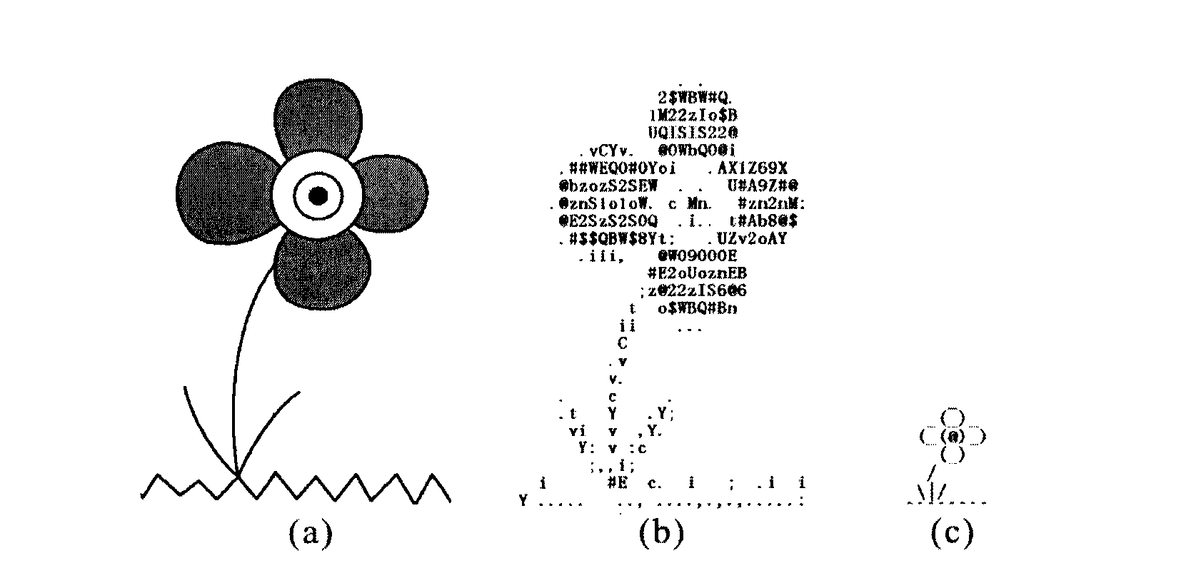
Methods and devices for producing structure-based ASCII pictures
A picture and equipment technology, applied in the direction of image data processing, graphics and image conversion, editing/combining graphics or text, etc., can solve problems such as inapplicability
- Summary
- Abstract
- Description
- Claims
- Application Information
AI Technical Summary
Problems solved by technology
Method used
Image


Examples
Embodiment approach 1
[0025] Reference image 3 The method 300 for generating an ASCII picture according to the first embodiment of the present application includes the following steps. In step 301, the input vector contour map is rasterized and divided into multiple grid units. In step 302, the image content in each grid cell is matched with an ASCII character by using a shape similarity measure based on imprecise alignment. Then, in step 303, the matched ASCII characters are collected together to generate an ASCII picture. In this method, the image to be processed may be a vector outline image containing only polylines. For other images such as photos, you can first use known simple edge detection methods or advanced line drawing generation methods to convert them into contour maps, and then vectorize them into vector contour maps. E.g, Figure 4 The image 401 shown in can be converted and vectorized into a corresponding vector outline image 402. The steps of rasterization and character matchin...
Embodiment approach 2
[0041] According to the second embodiment of the present application, the reference image is slightly deformed to improve the chance of matching suitable characters.
[0042] Picture 9 It is a flowchart of a method 900 according to the second embodiment. In step 901, an ASCII picture has been generated based on the input vector outline. This step can be implemented according to steps 301-303 in the first embodiment described above. It can be understood that the shape dissimilarity between each grid unit of the vector outline image and the matched ASCII character in the ASCII result picture can be obtained in step 901. Then, in step 902, the average shape dissimilarity between the vector contour map and the ASCII result picture is obtained by dividing the total shape dissimilarity by the number of non-empty grid cells. In step 903, the vector contour map is slightly deformed. For example, such deformation can be achieved by iteratively adjusting the vertex positions of the pol...
Embodiment approach 3
[0047] However, in the second embodiment described above, unconstrained deformation may destroy the overall structure of the input picture. In this case, the third embodiment is proposed to quantify the degree of deformation, and to select the ASCII picture with the smallest deformation.
[0048] In this embodiment, the degree of deformation of the vector image and the degree of dissimilarity between the character and the deformed picture are all considered. The flowchart of the method 1000 according to the third embodiment is as Picture 10 Shown. The third embodiment is very similar to the second embodiment, except for step 1006 and step 1007. In step 1006, a local deformation degree related to each line segment in the deformed vector contour map is calculated. In step 1007, the objective function is calculated based on the shape dissimilarity and the local deformation. These two steps will be explained in detail below. In addition, in this solution, the shape dissimilarity...
PUM
 Abstract
Description
Claims
Application Information