Imaging module

A technology of camera module and camera element, which is applied in the direction of image communication, TV, color TV parts, etc., and can solve problems such as insufficient thread fastening strength, image quality deterioration, and camera module water resistance decline, etc.

Active Publication Date: 2012-01-04
KYOCERA CORP
View PDF7 Cites 9 Cited by
  • Summary
  • Abstract
  • Description
  • Claims
  • Application Information

AI Technical Summary

Problems solved by technology

[0007] On the other hand, in order to reduce the size of the camera module and reduce the size of the screw fastening part, if the diameter of the screw is reduced, the strength of the screw fastening will be insufficient.
In this way, when the bracket is screwed onto a motor vehicle or the like, the vibration of the motor vehicle or the like weake

Method used


Image

  • Imaging module
  • Imaging module
  • Imaging module

Examples


Embodiment

[0055] Hereinafter, an embodiment of the camera module 1 of the present invention will be described.

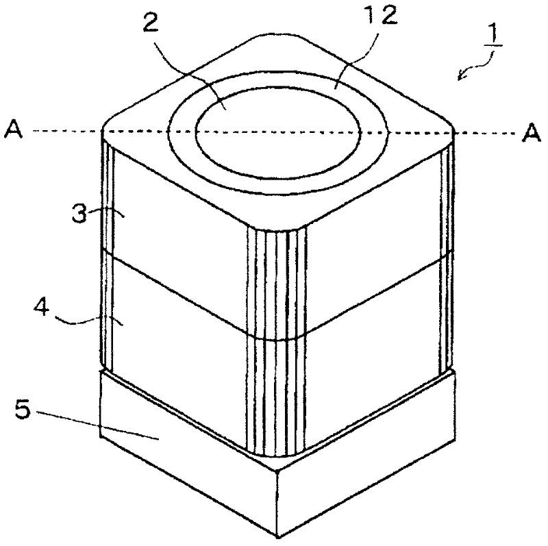
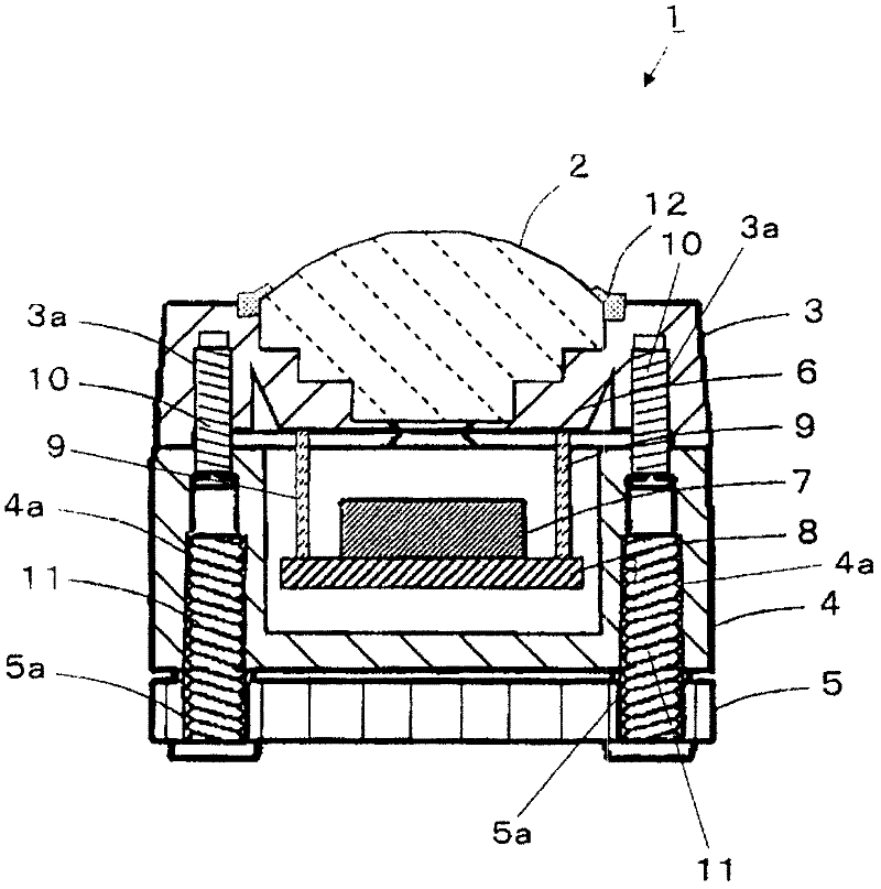
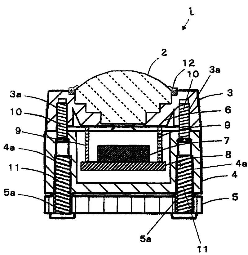
[0056] figure 1 and figure 2 The camera module of the embodiment of the structure shown is fabricated as follows. First, a rectangular cylindrical front cabinet 3 made of polycarbonate formed by injection molding and a square box-shaped rear cabinet 4 made of polycarbonate formed by injection molding are prepared. In the front case 3, the square cross section has dimensions of 23 mm in length and 23 mm in width and 10 mm in height. In the rear case 4, the square cross section has dimensions of 23 mm in length and 23 mm in width and 13 mm in height. Furthermore, the front case 3 has a cylindrical lens barrel 6 inside.

[0057] Next, the lens unit 2 composed of three lenses is installed on the lens barrel 6 inside the front case 3 , and the lens unit 2 is fixed by the ring-shaped retainer 12 . Moreover, the connection terminal 9 provided on the lens barrel 6 inside the fro...


PUM


Abstract

Screw-fastening sections for attaching a front case, a back case, and a bracket can be made smaller, high screw-fastening strength can be maintained, and when the bracket is installed on an automobile or the like using screws, changes in the length of the optical axis between a lens unit and an imaging element and shifting of the optical axis can be prevented. An imaging module (1) is provided with a front case (3) that has a lens unit (2) installed on the photographic subject side, a back case (4) that is attached to the front case (3) such that an imaging substrate (8) is sealed inside an inner space formed with the front case (3), and a bracket (5) that is attached to the back case (4). The back case (4) is attached to the front case (3) by means of screw holes (3a) and first screws (10) that are screwed into first screw-fastening through-holes (4a), and the bracket (5) is attached to the back case (4) by means of the first screw-fastening through holes (4a) and second screws (11) that have a diameter larger than that of the first screws (10) and are screwed into second screw-fastening holes (5a).

Description

technical field [0001] The present invention relates to an imaging module using an imaging element including a semiconductor image sensor typified by a CCD image sensor. Background technique [0002] A conventional camera module having a bracket for mounting on an automobile or the like has, for example, the following structure. [0003] Specifically, the structure includes: a front case in which the lens unit is installed on the subject side, and an imaging substrate on which the imaging element is mounted is provided at a position opposite to the subject side, and the imaging element and the lens unit opposite; the rear shell, which is installed on the front shell to seal the imaging substrate in the inner space of the rear shell and the front shell; the bracket, which is installed on the rear shell. [0004] In the conventional camera module having such a structure, the front case and the rear case are screwed together by the first screw, and the rear case and the bracke...

Claims


Application Information

Patent Timeline
IPC IPC(8): H04N5/225
CPCH04N5/2252H04N5/2253H04N5/2257H04N23/51H04N23/54H04N23/57
Inventor 森岛理洋辻克美
Owner KYOCERA CORP
Why Eureka
Try Eureka