Apparatus and method for friction stir welding

A friction stir and joining device technology, applied in welding equipment, non-electric welding equipment, metal processing equipment, etc., to achieve good friction stir welding effect

Active Publication Date: 2012-02-15
KAWASAKI HEAVY IND LTD
View PDF7 Cites 10 Cited by
  • Summary
  • Abstract
  • Description
  • Claims
  • Application Information

AI Technical Summary

Problems solved by technology

[0024] Therefore, even if the air cylinder is disconnected to make the pressurizing force zero, at least the pressing force of the joint head's own weight is applied to the jointed parts, and it is not possible to realize the joining of soft materials or thin parts. sufficiently small pushing force

Method used


Image

  • Apparatus and method for friction stir welding
  • Apparatus and method for friction stir welding
  • Apparatus and method for friction stir welding

Examples


Embodiment Construction

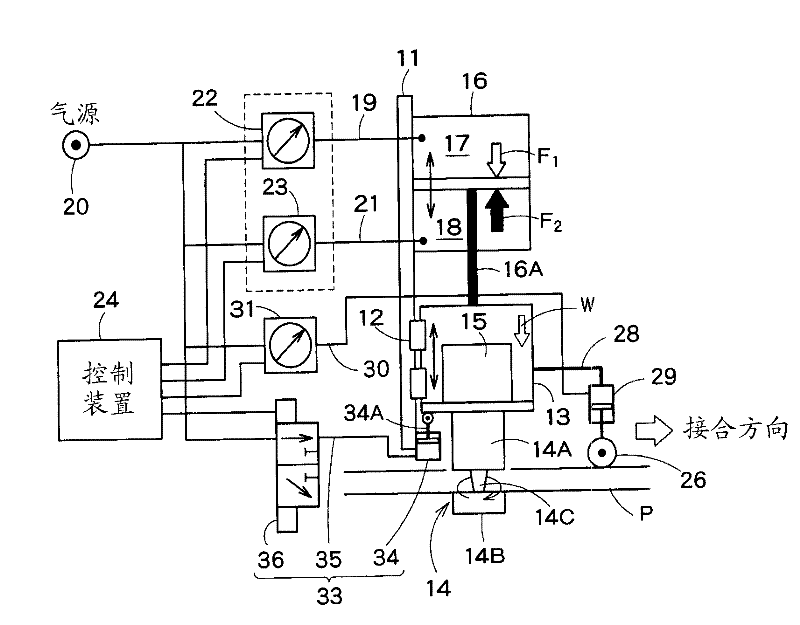
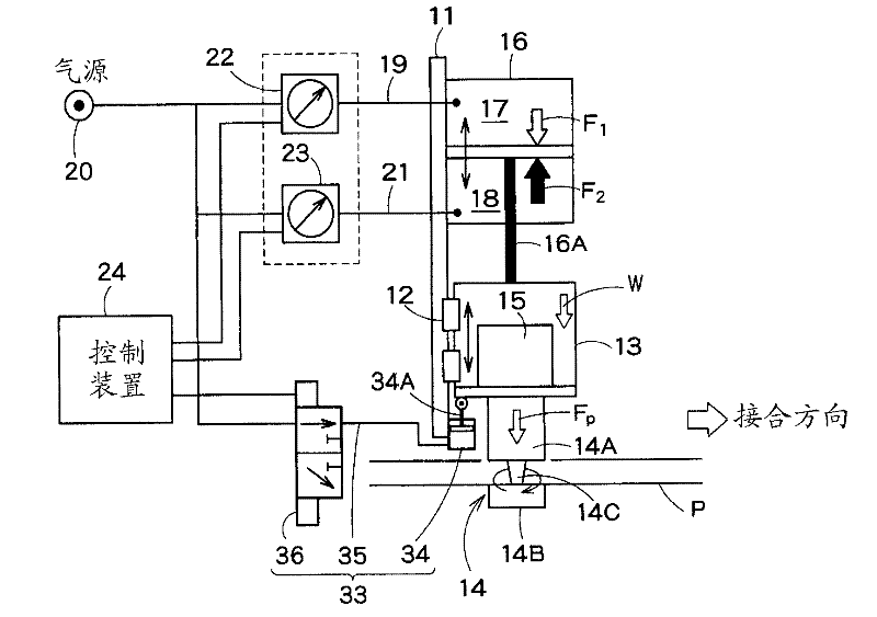
[0061] Hereinafter, a friction stir welding apparatus and its method as one embodiment of the present invention will be described with reference to the drawings.

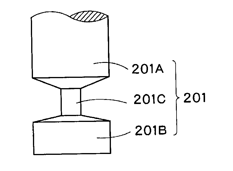
[0062] like figure 1 As shown, the friction stir welding apparatus 10 of this embodiment has the welding head 13 which is attached to the head support part 11 of the apparatus main body so that it can move linearly up and down via the linear guide 12. A bonding tool 14 that contacts the member P to be bonded during the bonding operation is rotatably attached to the bonding head 13 , and the bonding tool 14 is driven by a tool rotation drive motor (rotation drive unit) 15 provided on the bonding head 13 . rotate.

[0063] An air cylinder (head drive unit) 16 for driving the head is fixedly provided on the head supporting portion 11 , and the bonding head 13 is attached to a piston rod 16A of the air cylinder 16 . In addition, instead of the air cylinder 16, another fluid pressure cylinder such as a hydraulic cylin...


PUM


Abstract

The present apparatus comprises: a welding head (13) including a welding tool (14) that comes into contact with the members to be welded (P) and a driving means (15) for rotating the welding tool (14); a head driving means (16) for driving and displacing the welding head (13) which includes a hydraulic cylinder (16) having a piston rod (16A) to which the joining head (13) is connected; first pressurizing means (19,20) for supplying pressurized fluid to a first chamber (17) of the hydraulic cylinder (16); second pressurizing means (21,20) for supplying pressurized fluid to a second chamber (18) of the hydraulic cylinder (16); and control means (22,23,24) for controlling the pressure of the pressurized fluid supplied by the first (19,20) and the second pressurizing means (21,20).

Description

technical field [0001] The present invention relates to a friction stir welding device, and more particularly, to a friction stir welding device and a method thereof that perform welding by abutting a rotating welding tool against a member to be joined to generate plastic flow. Background technique [0002] Friction stir welding devices have been used in many fields such as railway vehicles, ships, aircrafts, and bridges in recent years. [0003] As a representative of a conventional friction stir welding device, there is a device that presses the joining tool against one surface of the member to be joined while rotating it, so that plastic flow occurs at the joining site, and the joint is formed by the plastic flow. The mixed material solidifies and joins the two parts together (Patent Document 1). As means for realizing the pressing force of the joining tool, in Patent Document 1, a push type air cylinder is used. [0004] Figure 8 The schematic structure of this type o...

Claims


Application Information

Patent Timeline
Patent Type & Authority Applications(China)
IPC IPC(8): B23K20/12
CPCB23K20/123B23K20/1245B23K20/125B23K20/12
Inventor 西田英人藤本光生神冈光浩冈田豪生
Owner KAWASAKI HEAVY IND LTD
Why Eureka
Try Eureka