Friction stir welding method

A friction stir and joining method technology, applied in welding equipment, metal processing equipment, manufacturing tools, etc., to achieve good friction stir welding effect

Inactive Publication Date: 2007-09-05
HITACHI LTD
View PDF3 Cites 9 Cited by
  • Summary
  • Abstract
  • Description
  • Claims
  • Application Information

AI Technical Summary

Problems solved by technology

[0014] As described above, there are cases where the defective portion 72 in the friction stir welding direction appears on the friction stir welding portion 70

Method used


Image

  • Friction stir welding method
  • Friction stir welding method
  • Friction stir welding method

Examples


Embodiment Construction

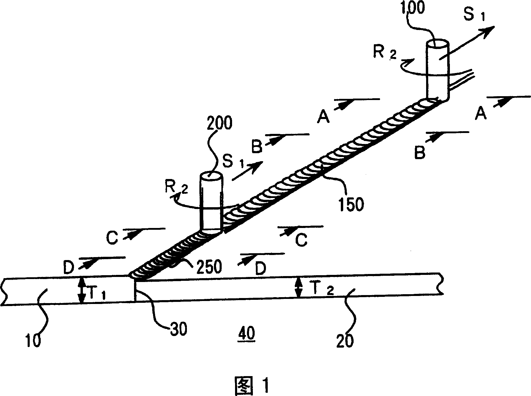
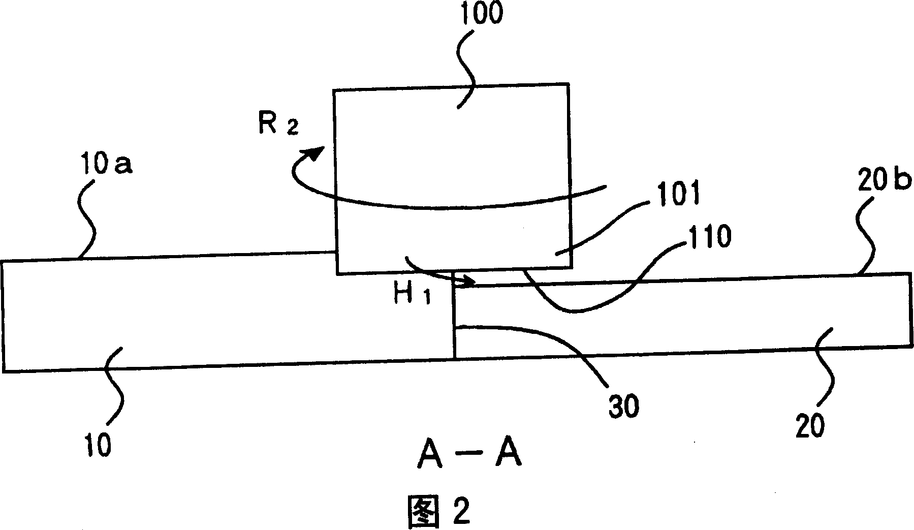
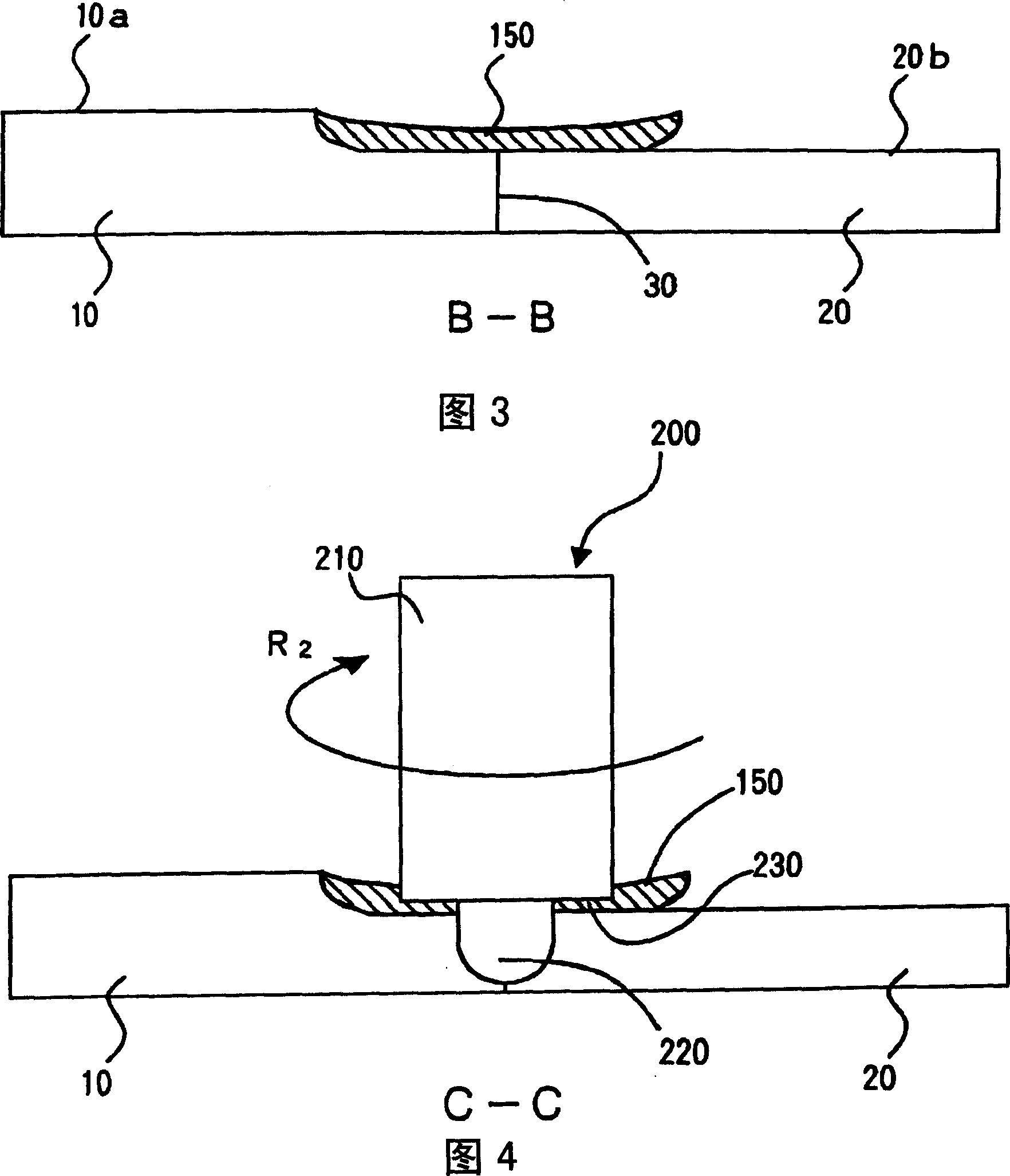
[0039] An embodiment of the friction stir welding method of the present invention will be described with reference to FIGS. 1 to 6 . The joining conditions of the first member 10 and the second member 20 are the same as those described with reference to FIGS. 14 and 15 .

[0040] That is, it is a method of performing friction stir welding on the abutment portion 30, wherein the abutment portion 30 will have a thickness dimension T 1 of the first component 10 with a thickness dimension T less than 1 The thickness dimension T 2 The second part 20 is docked. The first component and the second component are aluminum alloy. The second part 20 with a smaller thickness is located on the right-hand side of the first part in FIGS. 1 to 4 .

[0041] The friction stir welding method of the present invention includes two steps.

[0042] In the first step, before the friction stir welding of the mating portion 30 , the convex portion replacement portion 150 is formed on the upper surf...


PUM


Abstract

There is provided a friction stir welding method for forming a satisfactory weld portion by two steps when members having different thicknesses are butted together and friction stir welded. A first member 10 having a thickness T 1 and the second member 20 having a thickness T 2 , which is smaller than the thickness T 1 , are placed on a table 40 to form a stepped butt portion 30. In a first step, metal is transferred from the first member 10 to the second member 20 to form a convex substitute portion 150 in the stepped portion by rotatingly moving a columnar tool 100 along the butt portion 30. In a second step, friction stir welding is performed on the convex substitute portion 150 to obtain a satisfactory weld portion 250 by using a friction stir welding tool 200.

Description

technical field [0001] The present invention relates to a friction stir welding method suitable for joining members having different thickness dimensions at a butt-joint position. Background technique [0002] 14 and 15 are conventional explanatory diagrams showing a state in which members 10 and 20 having different thickness dimensions are butted and friction stir welded. (a) of each figure is a perspective view of a friction stir weld part. Fig. 14(b) is a F-F sectional view of (a). Fig. 15(b) is a G-G sectional view of (a). FIG. 14( a ) is a diagram when the friction stir welding tool 50 is inserted into the first member 10 and the second member 20 . [0003] For example, the first component 10 has a thickness dimension T 1 plate, the second component 20 is a thickness dimension T 2 parts. Thickness dimension T 1 greater than T 2 . Therefore, when the two parts are placed on a flat base 40 such as a table, a dimension G is generated on the upper surface of the ab...

Claims


Application Information

Patent Timeline
Patent Type & Authority Applications(China)
IPC IPC(8): B23K20/12
CPCB23K20/122B23K20/129B23K20/1245B23K20/24
Inventor 江角昌邦
Owner HITACHI LTD
Why Eureka
Try Eureka