Fluorescent display tube

A fluorescent display tube and anode technology, applied in the field of fluorescent display tubes, can solve the problems of digital grid shape and complex combination, and achieve the effect of reducing the number of installation man-hours and high-density fluorescent display tubes

Inactive Publication Date: 2010-04-21
FUTABA CORPORATION
View PDF7 Cites 0 Cited by
  • Summary
  • Abstract
  • Description
  • Claims
  • Application Information

AI Technical Summary

Problems solved by technology

[0008] On the other hand, with the expansion of the use of fluorescent display tubes, the shape and combination of grids that constitute digits have become more complicated.

Method used


Image

  • Fluorescent display tube
  • Fluorescent display tube
  • Fluorescent display tube

Examples


Embodiment Construction

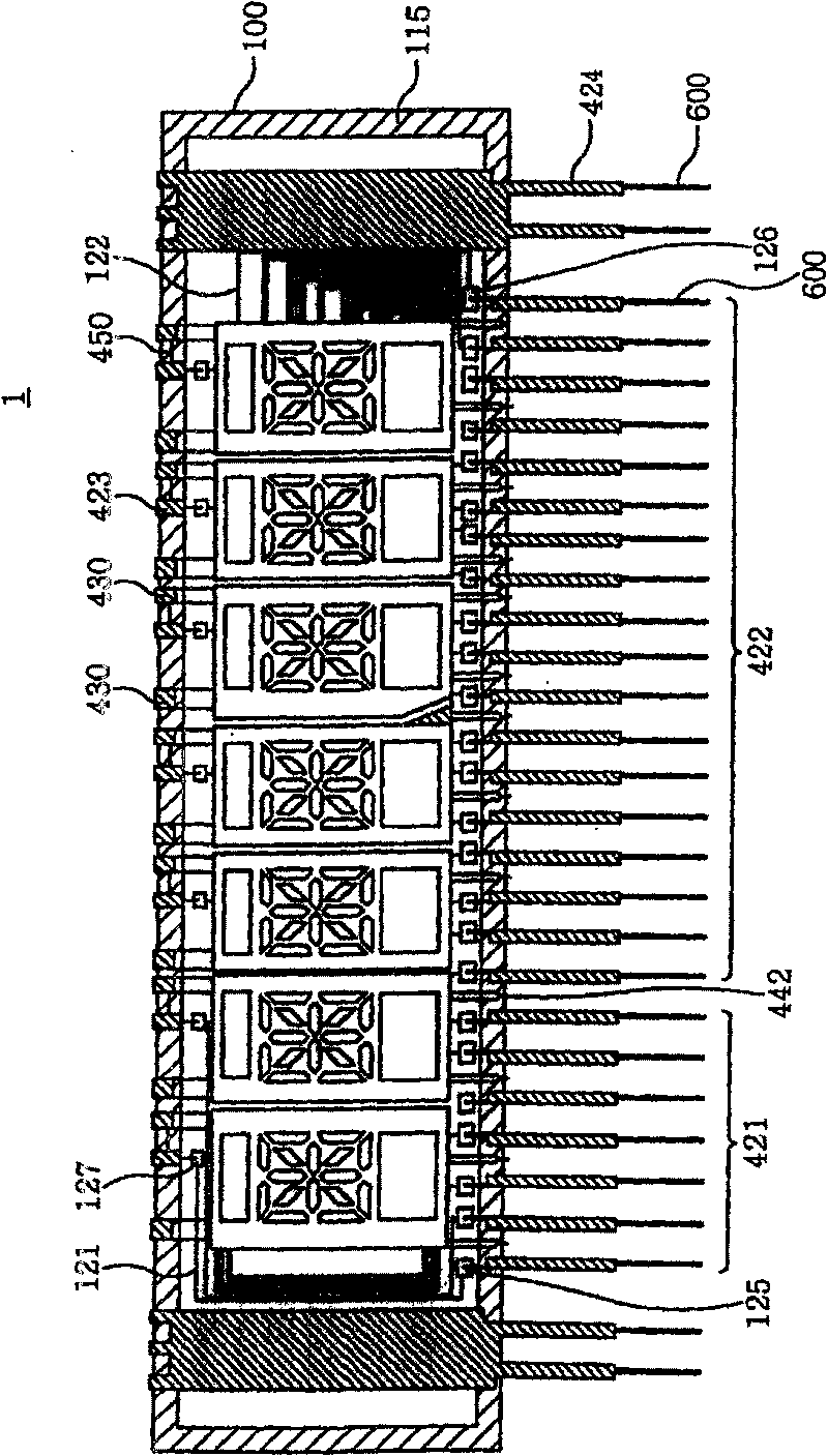
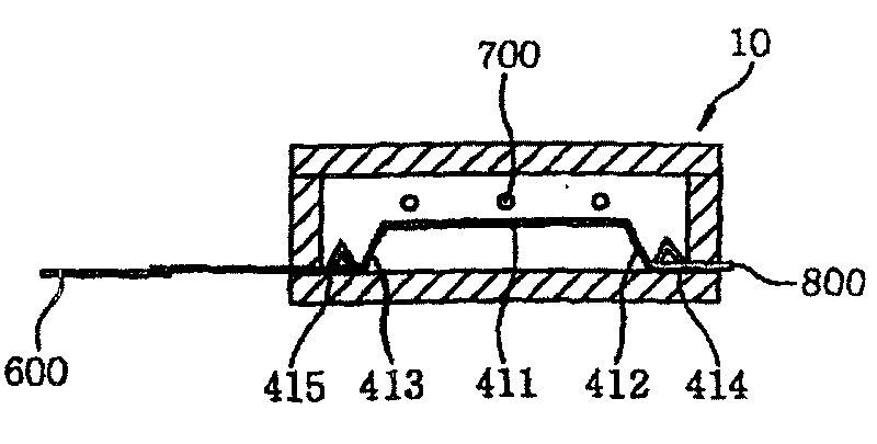
[0108] Below to Figure 1A-1D as well as figure 2 Based on this, the fluorescent display tube of the present invention will be described.

[0109] (Formation of anode substrate)

[0110] An aluminum film layer is arranged on the upper surface of an insulating substrate (110) made of soda-lime glass, and then a wiring layer is formed by photolithography, and the wiring layer includes: (i) gate wiring (121); (ii) ) electrically connecting the gate wiring (121) and the gate terminal A (127) of the gate (410); (iii) electrically connecting the gate for energizing the gate wiring (121) from the outside The gate terminal B (125) of the wire (421); (iv) the anode wire (122); (v) the anode wire (422) electrically connected to the anode wire (422) for energizing the anode wire (122) from the outside; Extreme (126).

[0111] Next, in order to cover the wiring layer, an insulating layer (130) is formed by using a paste mainly composed of low-melting glass and a pigment by a thick fi...


PUM


Abstract

To provide a dynamic drive fluorescent display tube easy for handling and having a plurality of cheeper grids. The dynamic drive fluorescent display tube has an assembly including a grid having an opening of the form of a mesh on a metal thin plate having a thickness of 0.1mm-0.15mm, a connecting member A B for fixing the grid to a vacuum sealed container, a connecting member for connecting the connecting member A and the grid to a grid wiring, and a lead for connecting the grid wiring and a positive pole wiring. A plurality of grids are formed by connecting each grids with grid wirings on a cathode substrate, and placing the grids and positive pole leads into different areas.

Description

technical field [0001] The invention relates to the improvement of grids used in fluorescent display tubes and a dynamically driven fluorescent display tube with multiple grids. Background technique [0002] A fluorescent display tube has a vacuum-tight container in which a high vacuum state is maintained. An anode conductor and a phosphor layer are formed on the upper surface of an insulating substrate made of a glass plate constituting a part of the vacuum airtight container to form an anode. Furthermore, a grid with grid-like openings is disposed above the phosphor layer, and the combination of the phosphor layer and the grid is used as a set of digits, and there are multiple digits in the same vacuum airtight container. . A filament is drawn above the grid. [0003] When the fluorescent display tube is in use, a filament current is supplied to the filament-shaped cathode from the outside through a wire, so that it emits thermal electrons. [0004] In the state of emi...

Claims


Application Information

Patent Timeline
Patent Type & Authority Patents(China)
IPC IPC(8): H01J29/02H01J29/46H01J31/12H01J31/15
Inventor 都仓胜司真神毅
Owner FUTABA CORPORATION
Why Eureka
Try Eureka