Liquid-coated gas desulfurizing/atomizing nozzle

An atomizing nozzle and air-encapsulated technology, which is applied in the direction of liquid injection devices, injection devices, chemical instruments and methods, etc., can solve the problems of high energy consumption, poor atomization effect, easy blockage, etc., and achieve high-efficiency atomization , Reduce daily maintenance costs, high atomization efficiency

Inactive Publication Date: 2012-03-28
SOUTH CHINA UNIV OF TECH
View PDF4 Cites 17 Cited by
  • Summary
  • Abstract
  • Description
  • Claims
  • Application Information

AI Technical Summary

Problems solved by technology

The atomization effect of this type of nozzle is not good, the energy consumption is high, and it is easy to block

Method used


Image

  • Liquid-coated gas desulfurizing/atomizing nozzle
  • Liquid-coated gas desulfurizing/atomizing nozzle
  • Liquid-coated gas desulfurizing/atomizing nozzle

Examples


Embodiment Construction

[0022] The specific embodiments of the present invention will be described in further detail below, but the embodiments of the present invention are not limited thereto.

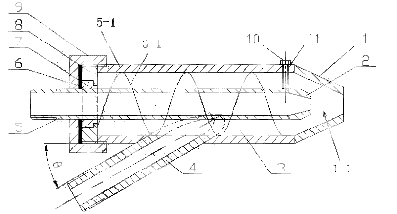
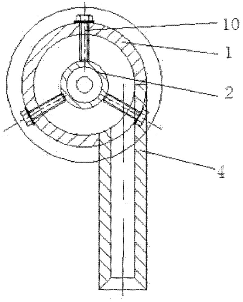
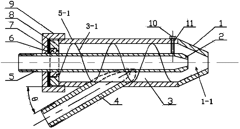
[0023] Such as figure 1 shown. The gas-in-liquid desulfurization atomizing nozzle of the present invention includes a slurry nozzle 1 with an inner tapered end and a gas nozzle 2 with an inner tapered end. The gas nozzle 2 is placed inside the slurry nozzle 1 and the axes of the two are the same. axis. There is a gap between the outer wall of the gas nozzle 2 and the inner wall of the slurry nozzle 1 (the size of the gap is determined by the diameters of the slurry nozzle 1 and the gas nozzle 2), and the gap constitutes the slurry cavity 3 of the slurry nozzle 1. The outer wall of the slurry nozzle 1 is provided with a slurry inlet pipe 4 . The diameter of the gas nozzle 2 outlet should be smaller than the diameter of the slurry nozzle 1 outlet. The tail end 5-1 of the slurry nozzle 1 and the tail end 5 ...


PUM


Abstract

The invention discloses a liquid-coated gas desulfurizing/atomizing nozzle which comprises an internal tapered slurry nozzle and an internal tapered gas nozzle, wherein the gas nozzle is arranged in the slurry nozzle, a gap is formed between the outer wall of the gas nozzle and the inner wall of the slurry nozzle, the outer wall of the slurry nozzle is provided with a slurry inlet pipe, and the internal circumferential surface of the slurry nozzle is a thread surface. Pressure gas subjected to pressurization is fed into the gas nozzle with an internal tapered end, further compressed, jetted out from the gas nozzle, and then converged with slurry in a tapered jet chamber of the slurry nozzle so as to form 'liquid-coated gas'; and under the action of high speed and pressure difference, the 'liquid-coated gas' is broken, and liquid drops are separated and broken and finally jetted out by the slurry nozzle, so that the slurry is efficiently atomized, thereby achieving an optimal flue gas desulfurization effect. The slurry inlet pipe is communicated with the gas nozzle in an obliquely-tangential direction, and the installation angle is consistent with the spiral angle of a thread structure, thereby further facilitating the formation of a natural spiral rotational flow when the slurry is fed into a slurry cavity, and facilitating the formation of the 'liquid-coated gas'.

Description

technical field [0001] The invention relates to a desulfurization atomization nozzle, in particular to a liquid-in-gas type desulfurization atomization nozzle. Background technique [0002] With the rapid development of thermal power plants, sulfur dioxide emissions are also increasing. The emission of sulfur dioxide is one of the main causes of air pollution and acid rain. How to implement desulfurization projects in coal-fired power plants, improve desulfurization process, and improve desulfurization efficiency are effective means to effectively curb sulfur dioxide emissions. Practice has shown that wet limestone-gypsum wet flue gas desulfurization technology is an efficient desulfurization technology and has been adopted by many large coal-fired power plants. However, at present, the investment in desulfurization equipment is high, and the operation and maintenance costs are high, resulting in high desulfurization costs. Therefore, it is of great economic significance ...

Claims


Application Information

Patent Timeline
Patent Type & Authority Applications(China)
IPC IPC(8): B01D53/80B01D53/50B05B7/04
Inventor 刘定平黄群亮张竞争刘畅
Owner SOUTH CHINA UNIV OF TECH
Why Eureka
Try Eureka