Device for realizing foldback panoramic and telescopic combination imaging by using non-spherical reflector and method thereof

A technology of combining imaging and mirrors, which is applied in the direction of optical components, optics, instruments, etc., can solve the problems of increased manufacturing cost and manufacturing difficulty, inability to achieve compact structure, and small image magnification, so as to maximize and realize Effective Pixel Utilization Effect

Active Publication Date: 2013-06-05
ZHEJIANG UNIV
View PDF3 Cites 0 Cited by
  • Summary
  • Abstract
  • Description
  • Claims
  • Application Information

AI Technical Summary

Problems solved by technology

On the other hand, due to its ultra-wide-angle characteristics, the panoramic optical system has a small image plane magnification. To achieve partial magnification of a certain area on the annular image, one way is to use a larger sensor or a sensor with a higher pixel density. , this method cannot reduce the image area occupied by the central lens, and the volume of the overall system will become larger, and the manufacturing cost and difficulty will be greatly increased; another method is to add another set of telephoto near it The optical system is used as an auxiliary, but this will increase the complexity of the system, and because of its existence, it will also occupy part of the field of view in the image plane, forming a visual blind spot at a certain angle. In addition, it is interesting to quickly turn to the image plane of the panoramic system The area is also more difficult, so the real-time performance is poor, and the compactness of the structure cannot be achieved

Method used


Image

  • Device for realizing foldback panoramic and telescopic combination imaging by using non-spherical reflector and method thereof
  • Device for realizing foldback panoramic and telescopic combination imaging by using non-spherical reflector and method thereof

Examples


Embodiment Construction

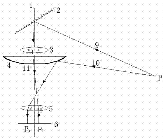
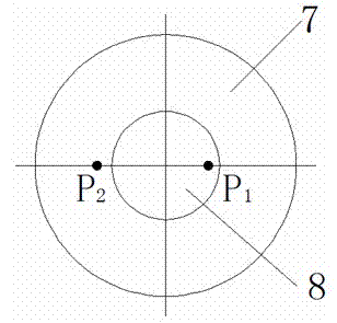
[0010] Such as figure 1 , 2 As shown, the turning-back panoramic telescopic combined imaging device realized by using an aspheric mirror is: a mirror 2, a telescope group 3, an aspheric mirror 4, an imaging mirror group 5 and a detection surface 6 are sequentially arranged on the optical axis 1 , the focal length of the telescope group 3 is 90mm~100mm, the focal length of the imaging mirror group 5 is 10mm~15mm, the central air gap between the telescope group 3 and the imaging mirror group 5 is 80mm~100mm, and the outer diameter of the aspheric mirror 4 is 100mm~ 120mm, the diameter of the central through hole 11 is 20mm~30mm, the conic coefficient is -1.5~-2.0, the radius of curvature is 150mm~200mm, the convex side is placed downward, and the lower surface is coated with reflective film for reflecting light. The optical axis 1 rotates to guide the light into the telescope group 3 and the imaging mirror group 5 below.

[0011] Utilize the aspheric reflector to realize the r...


PUM


Abstract

The invention discloses a device for realizing foldback panoramic and telescopic combination imaging by using non-spherical reflector and a method thereof. A light ray from an object point is reflected by the non-spherical reflector and is refracted on an image surface along with an imaging lens to form an annular belt image; and the other light ray from the object point moves downwardly to a telescope set and an imaging lens set coaxially arranged after being reflected by the reflector and is imaged in a central blind area of the annular belt image surface to form a locally amplified image. Two image surfaces are clearly imaged on the same plane and are not mutually overlapped by changing curvature of each lens of the telescope set, curvature radius of each lens of the imaging lens set and distance between the two lens sets. The device uses the optical system formed by combining two coaxial lens sets to image the same object point in the annular belt object space into the central blind area and the annular belt image surface respectively, so that original area of the center wasted by self imaging of camera is utilized, and panoramic and telescopic functions are realized while single sensor is used.

Description

technical field [0001] The invention relates to a lens imaging device and a method thereof, which can realize two functions of panoramic observation and partial telescopic zoom through a single sensor. Background technique [0002] Panoramic imaging technology based on catadioptric reflection is an imaging technology that combines traditional cameras and mirrors. It uses mirrors to reflect light from a large field of view into light with a smaller field of view, so that only ordinary cameras and lenses can be used to achieve panoramic and wide-range target monitoring. Different from refraction panoramic systems, this structure is more suitable for monitoring Panoramic area in 360° space behind the detector. Most of these panoramic systems use continuous spherical or conical surfaces as reflectors to collect wide-angle light. The fold-back panoramic imaging optical system has the characteristics of large field of view, simple structure, and easy implementation. It is su...

Claims


Application Information

Patent Timeline
Patent Type & Authority Patents(China)
IPC IPC(8): G02B17/08G02B13/02G02B13/06
Inventor 黄治白剑
Owner ZHEJIANG UNIV
Why Eureka
Try Eureka