
Double-channel common-image-plane panoramic annulus optical imaging device

An optical imaging, dual-channel technology, applied in the exploration of optical devices, the use of optical devices, optics, etc., can solve the problems of unsatisfactory promotion and application effects

Inactive Publication Date: 2020-05-22
ZHEJIANG UNIV
View PDF8 Cites 1 Cited by
  • Summary
  • Abstract
  • Description
  • Claims
  • Application Information

AI Technical Summary

Problems solved by technology

However, the field of view that the panoramic ring optical system pays attention to when it is used is a cylindrical area that surrounds the system 360° on the side, so the central small field of view light entering the optical system is not ideal for actual promotion and application.

Method used


Image

  • Double-channel common-image-plane panoramic annulus optical imaging device
  • Double-channel common-image-plane panoramic annulus optical imaging device

Examples


Embodiment Construction

[0018] The purpose and effects of the present invention will become clearer by describing the present invention in detail according to the accompanying drawings and preferred embodiments. It should be understood that the specific embodiments described here are only used to explain the present invention, not to limit the present invention.

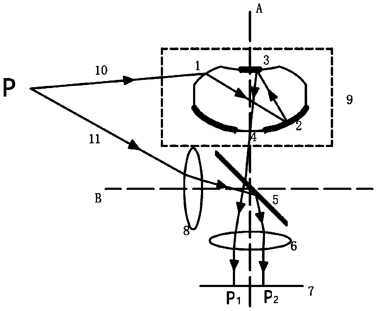
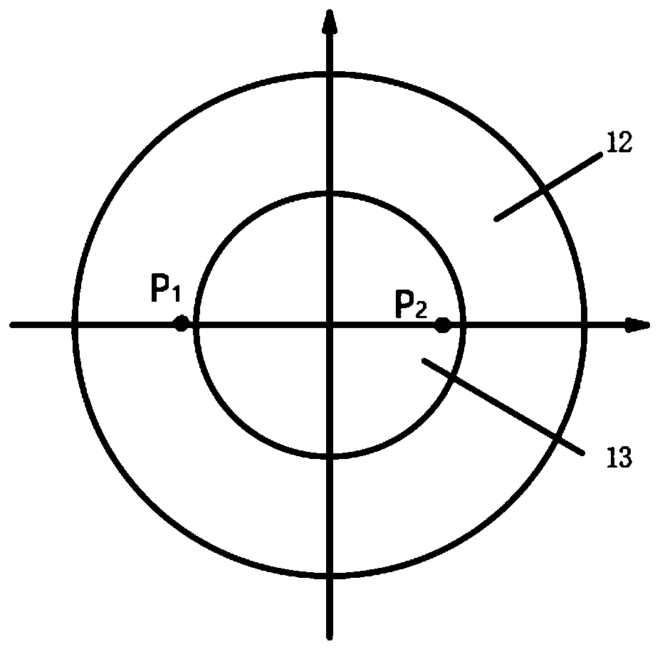
[0019] The panoramic annulus optical imaging device of the dual-channel common image plane proposed by the present invention, when the optical axis A of the optical path of the panoramic annulus is placed vertically on the ground, a half-transparent and half-mirror 5 is added before the follow-up lens group 6, and the light of the telescopic optical path It enters the telescopic lens group at a certain angle along the horizontal optical axis B, and enters the follow-up lens group 6 after being reflected by the half-mirror at 45°, and reaches the central circular area of ​​the detector target surface 7 for imaging. The field of view in the p...


PUM


Abstract

The invention discloses a double-channel common-image-plane panoramic annulus optical imaging device, which comprises a panoramic annulus optical system and a lateral view field telescopic optical system, and is characterized in that a cylindrical surface large-view-field panoramic annulus optical system is used for detecting the contour of an object around the optical system; detail features of atarget object are observed by using the lateral view field telescopic optical system; the two systems share one detector, the separated front half parts of the two light paths are turned back througha semi-transparent semi-reflective mirror to enter the same subsequent lens group to reach a target surface of a detector for imaging, the panoramic annulus optical system forms annulus area imagingon an image surface, a telescopic system forms imaging in a circular area in the middle of an image surface annulus, and the two areas do not interfere with each other. According to the invention, target detection in a large view field range and detail amplification of a key target are realized, and target object detection and tracking are facilitated. By adopting a common optical path, the imaging utilization rate of the system to an image plane is improved, the axial size of the whole optical system is reduced, and the device is compact in structure and can be suitable for a severe working environment.

Description

technical field [0001] The invention relates to a lens imaging device, in particular to a panoramic annular optical imaging device with two channels and a common image plane. Background technique [0002] The panoramic annular optical system is based on the imaging method of the cylindrical plane projection method, which has the advantage of large field of view imaging, and can detect the 360° circular cylinder around the system. It has been widely used in space detection, security monitoring, machine vision, Smart home, pipeline endoscopy, unmanned driving and other fields. More and more applications require lightweight and detailed detection of optical systems with large fields of view. For example, in the monitoring of power transmission lines, avoid the use of multiple lenses for shooting or complex control systems to control lens rotation monitoring, and use a single panorama The ring optical system can realize the monitoring of objects in the 360° range around the tra...

Claims


Application Information

Patent Timeline
IPC IPC(8): G02B17/08G01B11/24G01V8/14
CPCG01B11/2433G01V8/14G02B17/08
Inventor 白剑王佳
Owner ZHEJIANG UNIV
Learn More