Device and method of using panorama zone lens for achieving panorama telescopic combination imaging

An annular lens and combined imaging technology, applied in optical components, optics, instruments, etc., can solve the problems of shrinking the central blind spot, increasing manufacturing cost and difficulty, and poor real-time performance, so as to make up for the blind spot.

Active Publication Date: 2012-06-20
ZHEJIANG UNIV
View PDF3 Cites 19 Cited by
  • Summary
  • Abstract
  • Description
  • Claims
  • Application Information

AI Technical Summary

Problems solved by technology

[0004] The panoramic annular imaging optical system has the characteristics of large field of view, compact size, and low manufacturing cost. , the first reflective surface blocks the front field of view, so there is a central blind area, which reduces the utilization rate of the effective pixels of the sensor, and the area of ​​this area will increase with the increase of the field of view, which is a serious defect; On the one hand, due to the ultra-wide-angle characteristics of the panoramic annular optical system, the size of the image formed on the detection surface is severely compressed. To achieve magnified observation of a certain area on the annular image, one way is to use a larger Sensors with higher or higher pixel density, but this method cannot reduce the area of ​​the central blind area, and the overall system will become larger, and the manufacturing cost and manufacturing difficulty will greatly increase. Another method is to increase the area near it. A set of telescopic optical system, this system will inevitably block part of the field of view of the ring image, and at the same time it is difficult to quickly turn to the area of ​​interest in the image plane of the panoramic ring system, so the real-time performance is poor, and it cannot be realized Compactness of structure

Method used


Image

  • Device and method of using panorama zone lens for achieving panorama telescopic combination imaging
  • Device and method of using panorama zone lens for achieving panorama telescopic combination imaging
  • Device and method of using panorama zone lens for achieving panorama telescopic combination imaging

Examples


Embodiment Construction

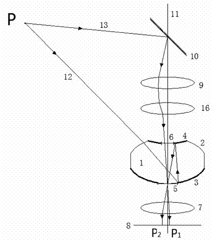
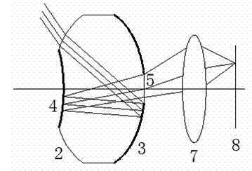
[0013] Such as figure 1 , 2 As shown, the panoramic telephoto composite imaging device realized by using the panoramic annular lens is: on the optical axis 11, a reflector 10, a telescope group 9, a connecting lens 16, a panoramic annular imaging lens 1, and a relay steering lens 7 are sequentially arranged. And the detection surface 8, one end of the panoramic annular band imaging lens 1 is provided with a convex first annular refraction surface 2, and the inner side of the first annular refraction surface 2 is provided with a concave second annular reflection surface 4, and the second concave annular reflection surface The inner side of the surface 4 is provided with a concave second refracting surface 6, and the other end surface of the panoramic annular imaging lens 1 is provided with a convex first annular reflective surface 3, and the inner side of the first annular reflective surface 3 is provided with a third refractive surface 5, The radius of curvature of the upper...


PUM


Abstract

The invention discloses a device and a method of using a panorama zone lens for achieving panorama telescopic combination imaging. A bunch of light sent from an object point images on an image surface through the panorama zone imaging lens, another bunch of light sent from the object point is reflected by a reflective mirror to spread downwards to enter a telescope group, a connecting lens, two refraction faces of the panorama zone imaging lens and a relay lens which are coaxially placed, and an image is formed in a middle blind area of the image surface of a panorama zone to form a partial amplification image. By changing curvature of the connecting lens, the distance between the connecting lens and the telescope group and the distance between the connecting lens and the panorama zone imaging lens, two clear image surfaces are on a same object point in a same plane and mutually free of overlapping. The device and the method of using the panorama zone lens for achieving the panorama telescopic combination imaging uses an optical system formed by combining two coaxially arranged lens groups, enables the same object point in an annular area to simultaneously image in the middle blind area and an annular zone image surface, solves the problem that the panorama zone imaging lens cannot image in the middle blind area, and achieves completion of double functions of panorama and telescoping by using a single sensor simultaneously.

Description

technical field [0001] The invention relates to a lens imaging device and a method thereof, in particular to a combined imaging device and method for realizing a panoramic telephoto by using a panoramic ring lens. Background technique [0002] The panoramic annular imaging technology based on the principle of planar cylindrical projection is a new imaging technology that is completely different from the traditional central projection principle. It can image the surrounding 360° annular scenery at one time without rotating the imaging system. A ring-shaped image surface realizes 360° panoramic staring imaging from the optical principle. As described in patents US Patent 4,566,763, 1986 and US Patent 5,473,474, 1995, the panoramic lens adopts the flat cylinder projection method FCP (Flat Cylinder Perspective), and projects the cylindrical field of view around the optical axis of the optical system within 360° to a two-dimensional plane. within a circular area. The panora...

Claims


Application Information

Patent Timeline
Patent Type & Authority Applications(China)
IPC IPC(8): G02B17/08G02B13/06
Inventor 黄治白剑侯西云
Owner ZHEJIANG UNIV
Why Eureka
Try Eureka