Contact position indicating device of automatic change-over switch

A technology for automatic transfer switches and indicating devices, which is applied in the direction of electric switches, contact drive mechanisms, electrical components, etc. It can solve problems such as wrong indication status, hidden dangers of maintenance safety, and inability to match the position of the contacts, etc., to achieve the effect of precise pointing

Active Publication Date: 2014-06-11
CHANGSHU SWITCHGEAR MFG CO LTD (FORMER CHANGSHU SWITCHGEAR PLANT)
View PDF2 Cites 0 Cited by
  • Summary
  • Abstract
  • Description
  • Claims
  • Application Information

AI Technical Summary

Problems solved by technology

[0005] To sum up, since the indication position of the indicator is converted by the motor drive, it cannot be consistent with the position of the contact, which easily provides the wrong indication state for the operator and maintenance personnel, and makes their operation and maintenance take a long time. A huge potential safety hazard and may cause unnecessary losses

Method used


Image

  • Contact position indicating device of automatic change-over switch
  • Contact position indicating device of automatic change-over switch
  • Contact position indicating device of automatic change-over switch

Examples


Embodiment 1

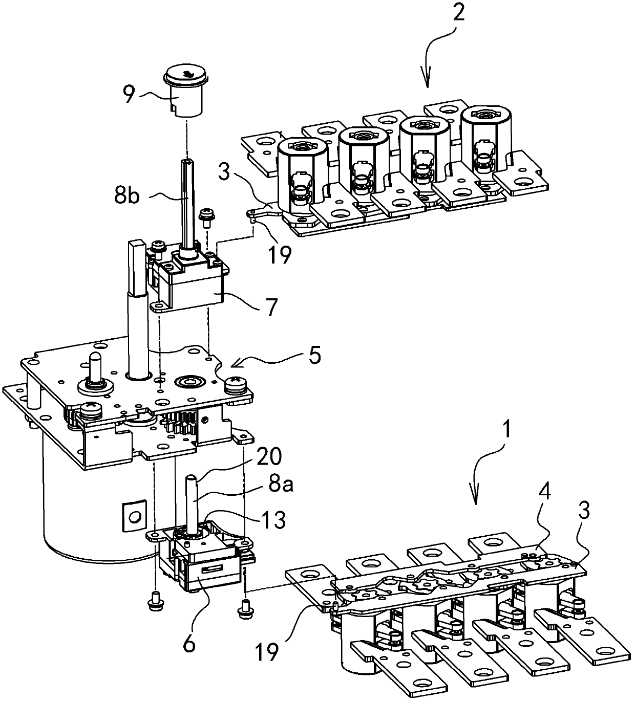
[0035] Embodiment one: see attached figure 1 ~ attached Figure 5c Shown:

[0036] A contact position indicating device for an automatic transfer switch, which is composed of a first transmission unit 6 , a second transmission unit 7 , an output shaft 8 and an indicator 9 .

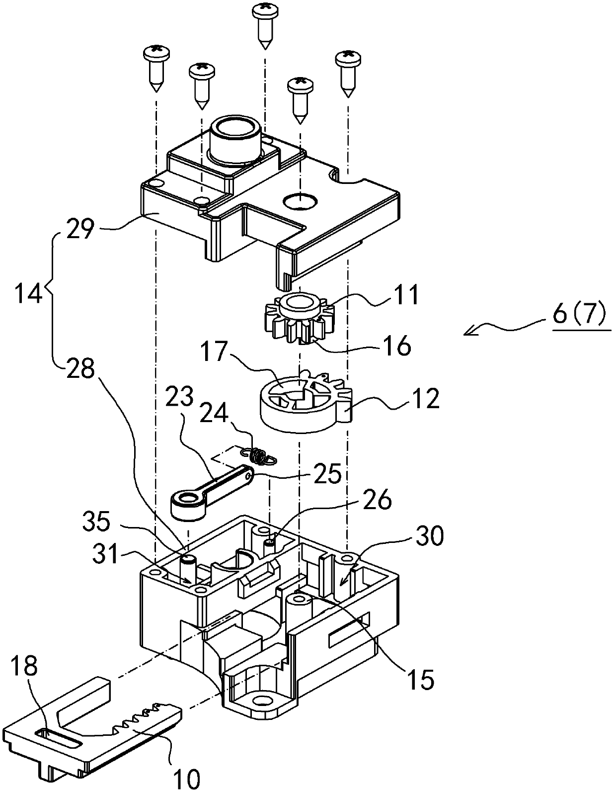
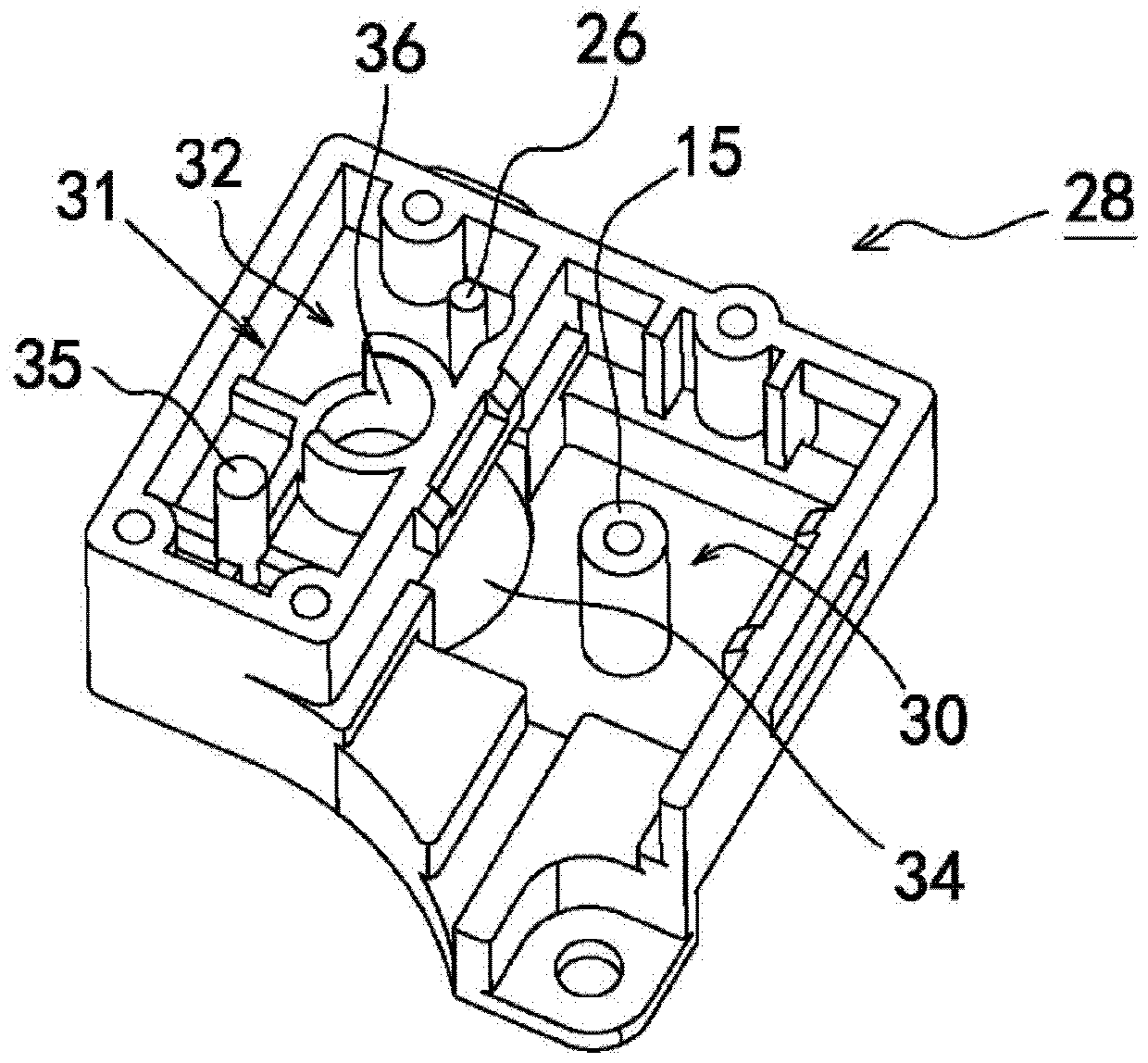
[0037] The first transmission unit 6 and the second transmission unit 7 have the same structure, see attached figure 2 As shown, each includes a rack 10 , a transmission gear 11 , a first split gear 12 , a second split gear 13 and a unit housing 14 . The housing of described rack 10 is slidably arranged relative to the automatic transfer switch, and concrete rack 10 is as follows: figure 2 The shown slide is plugged in the unit housing 14, the transmission gear 11 and the first split gear 12 are sleeved together on the support shaft 15 in the unit housing 14, and the transmission gear 11 and the first split gear 12 Fixed connection between them or positioning connection in the direction of rotation,...

Embodiment 2

[0048] Embodiment two: see attached Figure 6 , attached Figure 7 Shown:

[0049]A contact position indicating device for an automatic transfer switch, which is composed of a first transmission unit 6 , a second transmission unit 7 , an output shaft 8 and an indicator 9 . The difference from Embodiment 1 is that an over-position prevention structure is also designed, specifically on the outer edge of the first opening and closing gear 12, when the indicator 9 is in the common opening position of the standby power supply, it is close to the second opening. At the two opening and closing gears 13, a limit protrusion 37 is protruded; From the number of teeth, the tooth thickness of the first tooth is reduced to form a special-shaped tooth 38 to avoid the limiting protrusion 37 , while the second tooth 39 is in blocking fit with the outer edge surface 40 of the limiting protrusion 37 . See attached Figure 6 As shown, the limiting convex portion 37 extends around the outer ed...


PUM


Abstract

The invention discloses a contact position indicating device of an automatic change-over switch. The contact position indicating device is characterized by consisting of a first transmission unit, a second transmission unit, an output shaft and an indicating element; each of the first transmission unit and the second transmission unit respectively comprises a rack, a transmission gear, a first switching on / off gear and a second switching on / off gear; the transmission gear is meshed with the rack; the second switching on / off gear and the transmission gear are fixedly connected or are positioned and connected in the rotation direction; the second switching on / off gear and the first switching on / off gear are matched; the output shaft connects the second switching on / off gear of the first transmission unit and the second switching on / off gear of the second transmission unit coaxially, and one end of the output shaft is connected with the indicating element so as to drive the indicating element so that the indication element has three gear working positions, namely all common spare power supply switching off, common power supply switching on and spare power supply switching on. The indicating device provided by the invention is directly related to drive mechanisms of contact systems of a common power supply unit and a spare power supply unit, the synchronous action of the indicating element and a contact is realized, and the action situation of the contact is reflected truly.

Description

technical field [0001] The invention relates to the field of low-voltage electrical appliances, in particular to a contact position indicating device of a three-position automatic transfer switch. Background technique [0002] Three-position automatic transfer switch is an automatic power switching device, mainly used in hospitals, hotels and other important places that need to ensure uninterrupted power supply. The existing three-position automatic transfer switch generally includes a normal power supply unit, a backup power supply unit, an electric operating mechanism and a contact position indicating device; the normal power supply unit and the backup power supply unit include a contact system, an arc extinguishing system and a transmission device, etc. . The electric operating mechanism includes a motor, a deceleration mechanism and a clutch mechanism, which are used to drive the contact system in the normal power supply unit and the backup power supply unit to realize ...

Claims


Application Information

Patent Timeline
Patent Type & Authority Patents(China)
IPC IPC(8): H01H9/16H01H3/40
Inventor 沈惠新周振忠管瑞良顾怡文
Owner CHANGSHU SWITCHGEAR MFG CO LTD (FORMER CHANGSHU SWITCHGEAR PLANT)
Why Eureka
Try Eureka