Unlock instant, AI-driven research and patent intelligence for your innovation.

Accumulator assembly

A technology of pressure accumulators, components, applied in the direction of actuator accumulators, vehicle components, elements with teeth, etc.

Inactive Publication Date: 2012-05-09
GM GLOBAL TECH OPERATIONS LLC
View PDF3 Cites 3 Cited by
  • Summary
  • Abstract
  • Description
  • Claims
  • Application Information

AI Technical Summary

Problems solved by technology

However, such accumulators must be able to be selectively sealed against pressurized gas

Method used


Image

  • Accumulator assembly
  • Accumulator assembly
  • Accumulator assembly

Examples


Embodiment Construction

[0048] The following description is merely exemplary in nature and does not limit the invention, its application or uses.

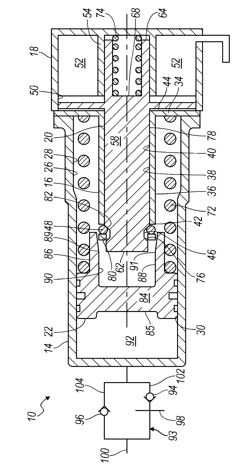
[0049] now refer to figure 1 and 2 , in which is shown a pressure accumulator assembly embodying the principles of the invention, generally designated by the reference numeral 10 . Accumulator assemblies are employed in the powertrain of a motor vehicle, which typically includes an engine and a transmission. Accumulator assembly 10 accumulates fluid directly or indirectly from a torque transmitting device (such as a clutch) when the vehicle's engine is on, conserves fluid when the engine is off, and discharges fluid directly or indirectly back to the torque transmitting device when the engine is restarted .

[0050] As its major components, the accumulator assembly 10 includes a valve body or housing 14 , an inner sleeve 16 , a solenoid body 18 , an armature 20 and a follower 22 . Valve body 14 is generally cylindrical and includes a bore surface 26 t...


PUM


Abstract

An accumulator assembly for a motor vehicle powertrain includes an armature and a follower. Together the armature and the follower can selectively lock together. The accumulator assembly may include a biasing member and a solenoid. When the solenoid is de-energized, the biasing member pushes the armature towards the follower to lock the armature and the follower together. When the solenoid is energized, the armature is magnetically drawn towards the solenoid and away from the follower to unlock the two components and to compress the biasing member.

Description

[0001] related application [0002] This application claims the benefit of US Provisional Application No. 61 / 391,309, filed October 8, 2010. The entire content of the above application is incorporated herein by reference. technical field [0003] The invention relates to a pressure accumulator of a power train in a motor vehicle. More specifically, the present invention relates to pressure accumulators with ball and ramp locking mechanisms. Background technique [0004] The statements in this section merely provide background information related to the present disclosure and may not constitute prior art. [0005] A typical vehicle powertrain includes an engine and a transmission. In some powertrains, the engine is selectively turned on or off. That is, when the vehicle comes to a stop, the engine is automatically stopped under a predetermined stop condition, and then, under a predetermined restart condition, the engine is restarted. These powertrains may also include a ...

Claims


Application Information

Patent Timeline
IPC IPC(8): B60K6/12
CPCF16H61/0021F15B2201/40F16H61/067F15B1/24F15B2201/21F15B2201/31B60Y2400/4185Y10T137/8659
Inventor C. E. 梅林L. 巴辛
Owner GM GLOBAL TECH OPERATIONS LLC