Structure for mounting camera on vehicle

A camera and vehicle technology, applied to vehicle components, transportation and packaging, optical observation devices, etc., can solve the problems of inconvenient camera attachment and detachment, and achieve the benefits of attachment/detachment operation, reduction of contact area, Effects that facilitate attachment/detachment operations

Active Publication Date: 2015-01-28
HONDA MOTOR CO LTD
View PDF8 Cites 0 Cited by
  • Summary
  • Abstract
  • Description
  • Claims
  • Application Information

AI Technical Summary

Problems solved by technology

[0005] Attachment and detachment of the camera to and from the vehicle are inconvenient when the camera is secured with bolts

Method used


Image

  • Structure for mounting camera on vehicle
  • Structure for mounting camera on vehicle
  • Structure for mounting camera on vehicle

Examples


no. 1 example

[0050] According to the first embodiment, the following effects can be achieved.

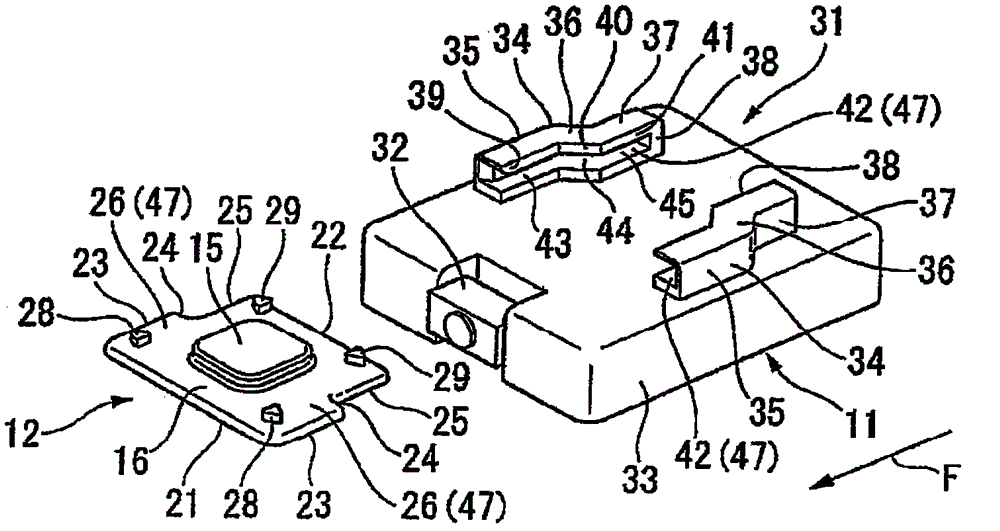
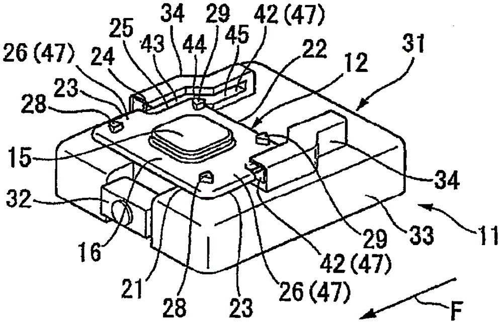
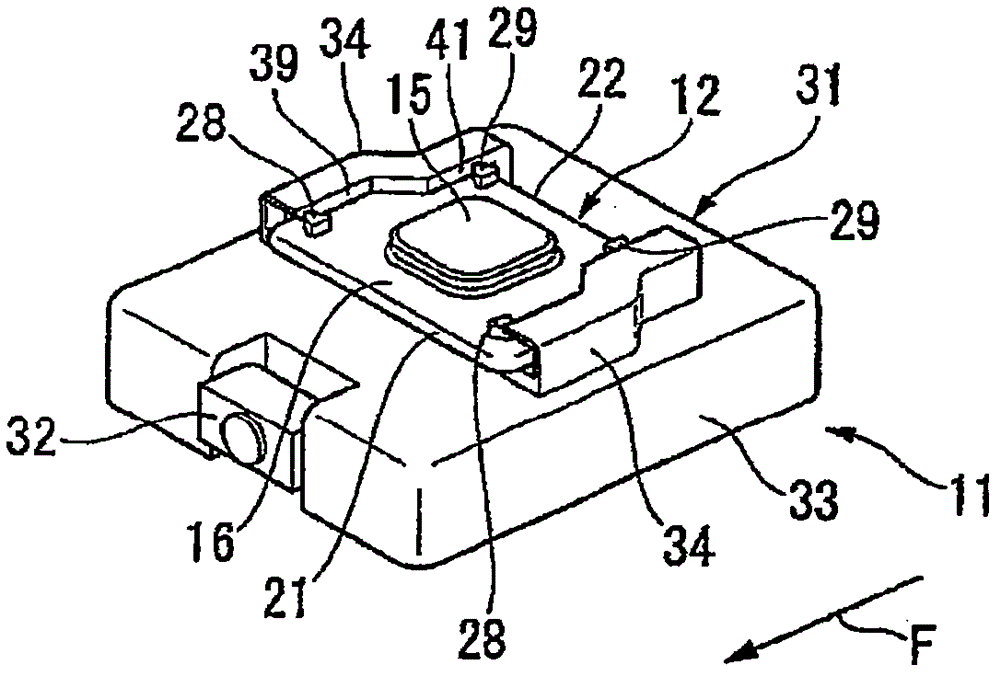
[0051] Since the camera 11 is slid to engage with the base unit 12 fixed to the vehicle body by the slide mechanism 47, the camera 11 can be easily attached / detached. The base unit 12 includes front side protrusions 28 and 28 and rear side protrusions 29 and 29 arranged transversely with respect to the attachment direction F so as to be in contact with the front side surface portions 39 and 39 and the rear side surface portions 41 and 41 of the camera 11. touch. Thus, positioning of the camera 11 in the lateral and rotational directions with respect to the base unit 12 can be easily performed, and shaking can be prevented. Since only the front side protrusions 28 and 28 and the rear side protrusions 29 and 29 contact the front side surface parts 39 and 39 and the rear side surface parts 41 and 41 laterally, the contact area can be minimized and the sliding resistance can be reduced, thereby Fa...


PUM


Abstract

One embodiment of the present invention provides a structure for mounting a camera on a vehicle, the structure including: a base unit fixed to a vehicle body; a camera; a slide mechanism configured to allow the camera to slide in an attaching direction so as to be detachably engaged with the base unit; protrusions provided on one of the base unit and the camera, the protrusions being disposed at front left and right sides and rear left and right sides with respect to the attaching direction; and contact portions provided on the other of the base unit and the camera, the contact portions laterally contacting the front left and right protrusions and the rear left and right protrusions, respectively, thereby positioning the camera with respect to the base unit.

Description

[0001] CROSS-REFERENCE TO RELATED APPLICATIONS [0002] This application claims priority from Japanese Patent Application No. 2010-239073 filed on October 25, 2010, the entire contents of which are hereby incorporated by reference. technical field [0003] The present invention generally relates to a structure for mounting a camera on a vehicle. Background technique [0004] Cameras may be mounted on vehicles such as automobiles to capture images of the vehicle's exterior. For example, a camera is used as part of a dash cam that records images of what is ahead of the vehicle. For example, in JP-2010-195235-A, in order to mount a camera on a vehicle, an attachment portion is fixed to a front windshield of the vehicle with double-sided tape, and then the camera is fixed to the attachment portion with bolts. [0005] When the camera is fixed with bolts, attachment and detachment of the camera to and from the vehicle is inconvenient. SUMMARY OF THE INVENTION [0006] An obj...

Claims


Application Information

Patent Timeline
Patent Type & Authority Patents(China)
IPC IPC(8): B60R11/04B60R1/00
CPCB60R11/04
Inventor 大西本泰真取忠弘
Owner HONDA MOTOR CO LTD
Why Eureka
Try Eureka