Indoor device of separable air conditioner

a technology of separable filters and air conditioners, applied in the field of separate types of air conditioners, can solve the problems of increasing manufacturing costs, insufficient purification of air, and replacement of separate filters, and achieve the effect of easy attachment/detachment of filters

Inactive Publication Date: 2008-04-01
LG ELECTRONICS INC
View PDF29 Cites 45 Cited by
  • Summary
  • Abstract
  • Description
  • Claims
  • Application Information

AI Technical Summary

Benefits of technology

[0021]Another object of the present invention is to provide an air conditioner having a structure making it easy to attach / detach a filter for purifying air.

Problems solved by technology

In the indoor unit of the air conditioner in accordance with the related art, only the air drawn in through the front air inlet 12 is purified by the front filter 14, but the air drawn in through the top air inlet having the top suction grill provided thereat is discharged to the room without being purified, resulting in a problem that the air is insufficiently purified.
When a separate filter is provided in the cabinet 10 to purify the air drawn in through the top air inlet, there is a problem that it is difficult to replace the separate filter and the structure of the cabinet becomes complicated, thereby increasing a manufacturing cost.

Method used


Image

  • Indoor device of separable air conditioner
  • Indoor device of separable air conditioner
  • Indoor device of separable air conditioner

Examples


first embodiment

[0072]FIG. 3 illustrates a perspective view showing an embodiment of an air conditioner with a filter unit in accordance with the present invention. FIG. 4 illustrates a perspective view showing the air conditioner of FIG. 3 in a stopping state. FIG. 5 illustrates showing a perspective view showing the air conditioner with a suction grill in accordance with the present invention. FIG. 6 illustrates a perspective view showing the air conditioner of FIG. 5 in a stopping state. FIG. 7 illustrates a perspective view showing an indoor unit provided at the air conditioner in accordance with the present invention.

[0073]FIG. 8 illustrates a perspective view showing a second embodiment of an air conditioner having a filter unit in accordance with the present invention. FIG. 9 illustrates a perspective view showing a second embodiment of the air conditioner with the suction grill in accordance with the present invention. FIG. 10 illustrates a perspective view showing a third embodiment of the...

second embodiment

[0103]Meanwhile, referring to FIGS. 8 and 9, an air conditioner with a display member 215b is illustrated, the display member 215b for displaying the operation information via avatar at a side of the front panel 215.

third embodiment

[0104]Referring to FIGS. 10 and 11, the air conditioner with the display member 215c is illustrated, the display member 215c displaying the operation information via a plurality of Avatars on a whole front surface of the front panel 215.

[0105]In the air conditioner illustrated in FIG. 8 to FIG. 11, since other structural elements are the same as stated above except the structural elements of each display member 215b and 215c, identical parts will be given the same names and reference symbols, and repetitive description of which will be omitted.

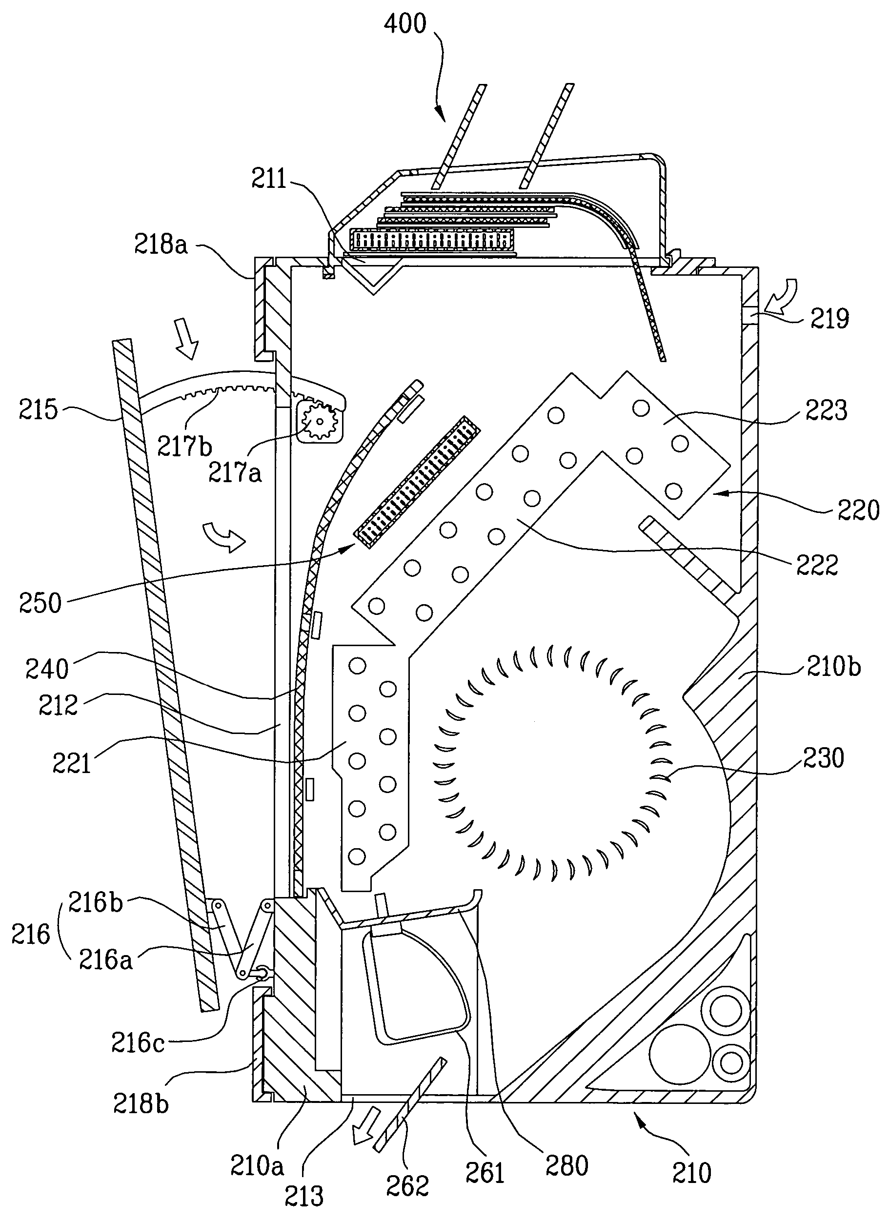
[0106]The first embodiment of the filter unit 400 provided at the air conditioner in accordance with the present invention will be described referring to FIGS. 12 to 15. FIG. 12 illustrates a cross sectional view showing an indoor unit of the air conditioner in accordance with the present invention, with a first embodiment of the filter unit. FIG. 13 illustrates a schematic perspective view showing the first embodiment of the filter unit provi...


PUM

PropertyMeasurementUnit
temperatureaaaaaaaaaa
humidityaaaaaaaaaa
pressureaaaaaaaaaa

Abstract

Disclosed is an air conditioner enabling to perform an air purifying function in an optimum state according to a pollution level of room air, the air conditioner including a cabinet having a first air inlet for drawing in the air, and an air outlet for discharging purified air, a fan provided at the cabinet and forcing the air movement, and a filter unit or a suction grill selectively provided at the first air inlet.

Description

CROSS-REFERENCE TO RELATED APPLICATIONS[0001]This application claims the benefit of Korean Application No. P2004-49732, filed on Jun. 29, 2004 and Korean Application No. P2004-54084, filed on Jul. 12, 2004, which are hereby incorporated by reference as if fully set forth herein.BACKGROUND OF THE INVENTION[0002]1. Field of the Invention[0003]The present invention relates to a separate type air conditioner, and more particularly, to an indoor unit of an air conditioner, provided in a room so as to cool / heat the room.[0004]2. Discussion of the Related Art[0005]In general, an air conditioner is an apparatus for controlling temperature and humidity of air in a particular area according to a use. As an example of the air conditioner, there is an apparatus having a compressor and a heat exchanger, and flowing a refrigerant so as to cool / heat an interior space such as a restaurant, a library, or an office. The air conditioner is divided into am integrated type air conditioner and a separate...

Claims


Application Information

Patent Timeline
Patent Type & Authority Patents(United States)
IPC IPC(8): F25D17/04F25D17/06F24F1/0073B01D19/00B01D45/00B01D46/00B01D47/00B01D49/00B01D50/00B01D51/00B01D53/00B01D57/00B01D59/00F24F1/0063F24F8/108F24F13/28F25B13/00
CPCF24F1/0007F24F3/166F24F13/28F24F3/1603F24F2001/0048F24F2003/1682F24F2003/1692F24F1/0057F24F8/192F24F8/30F24F8/60Y02A50/20F24F1/0073F24F1/0063F24F8/108
Inventor LEE, SANG HUNOCK, JU HOPARK, IN HEEBAE, JAE BUEMHUR, INN KUKIM, MYEONG SHIKKIM, YONG WOOWOO, CHANG YOON
Owner LG ELECTRONICS INC
Why Eureka
Try Eureka