Supercharge Your Innovation With Domain-Expert AI Agents!

Miniature rfid tag

A technology of radio frequency identification tags and inductance coils, applied in instruments, including printed electrical components, printed circuits, etc., can solve the problems of efficient operation obstruction and transmission of field-powered passive RFID tags

Active Publication Date: 2012-05-16
FLEXTRONICS AP LLC
View PDF3 Cites 2 Cited by
  • Summary
  • Abstract
  • Description
  • Claims
  • Application Information

AI Technical Summary

Problems solved by technology

[0005] Despite the cost, reliability, and environmental advantages of field-powered passive RFID tags, there are obstacles to efficient operation of field-powered passive RFID tags
Specifically, it may be difficult to deliver sufficient power from the base station to field-powered passive RFID tags via the interrogation signal

Method used


Image

  • Miniature rfid tag
  • Miniature rfid tag
  • Miniature rfid tag

Examples


Embodiment Construction

[0027] While the invention is susceptible to various modifications and alternative forms, specific embodiments thereof are shown by way of example in the drawings and described in detail herein. It should be understood, however, that there is no intention to limit the invention to the particular form disclosed, but the invention covers all modifications, equivalents and alternatives falling within the scope and spirit of the invention.

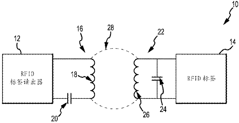
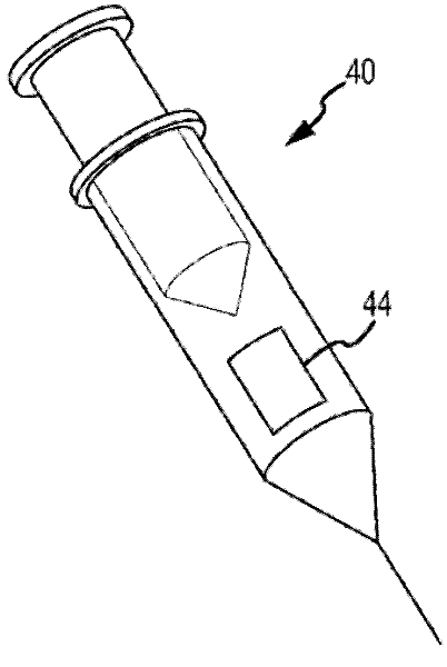
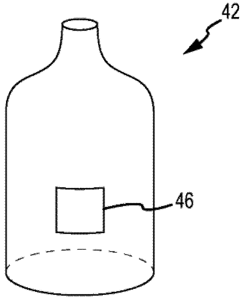
[0028] Embodiments disclosed herein relate to systems and related methods for providing miniature RFID tags that can be affixed or integrated into various devices including, but not limited to, medical products, disposable products, consumer products etc. The area of ​​an RFID tag can be substantially smaller, which can be advantageous in applications where size and / or weight are a concern. Furthermore, the costs associated with RFID tags can be relatively low due to material requirements and improved and simplified manufacturing methods. Mo...


PUM


Abstract

A technique for making an RFID tag that includes creating recesses or trenches in an insulated substrate. Conductive traces are created in the trenches so as to create an inductor coil for the RFID tag.

Description

[0001] Cross References to Related Applications [0002] Under 35 U.S.C. 119, this application claims priority to U.S. Provisional Application No. 61 / 170,836, filed April 20, 2009, entitled "Micro RFID Tags," the entire contents of which are hereby incorporated by reference. Background technique [0003] Radio Frequency Identification (RFID) transponders (tags) typically work in conjunction with RFID base stations (RFID readers) for various inventory control, security, and other purposes. Typically, an item with a tag associated therewith, such as a container with a tag on or within it, is placed into a "readout zone" established by the base station. An RFID base station may transmit an interrogation RF signal modulated by a receiving RFID tag. For example, an RFID base station may generate continuous wave (CW) electromagnetic interference at a certain (carrier) frequency, and this interference may be modulated by an RFID tag to correspond to data transmitted back to the base...

Claims


Application Information

Patent Timeline
Patent Type & Authority Applications(China)
IPC IPC(8): G06K19/077G06K19/07
CPCG06K19/07749H05K3/107H05K1/165G06K19/07783H05K3/426H05K2201/09036G06K19/07779G06K19/07758H04Q5/22
Inventor W.塔姆L.施特拉姆P.萨托里厄斯
Owner FLEXTRONICS AP LLC
Features
  • R&D
  • Intellectual Property
  • Life Sciences
  • Materials
  • Tech Scout
  • Unparalleled Data Quality
  • Higher Quality Content
  • 60% Fewer Hallucinations
Learn More