Pneumatic tire

A technology for pneumatic tires and tread rubber, which is applied to the reinforcement layers, tire parts, wheels and other directions of pneumatic tires, can solve the problems of not improving the wet braking performance and not being disclosed, and achieves improving the wet braking performance and ensuring the control The effect of stable performance

Inactive Publication Date: 2012-05-23
TOYO TIRE & RUBBER CO LTD
View PDF9 Cites 6 Cited by
  • Summary
  • Abstract
  • Description
  • Claims
  • Application Information

AI Technical Summary

Problems solved by technology

However, this tire does not disclose a structure for appropriately amplifying the shear strain in the tire front-rear direction generated by the tread rubber, and it is considered that there is almost no effect of improving wet braking performance.

Method used


Image

  • Pneumatic tire
  • Pneumatic tire
  • Pneumatic tire

Examples


Embodiment approach

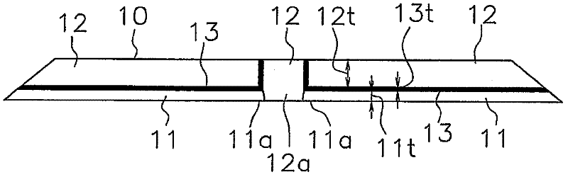
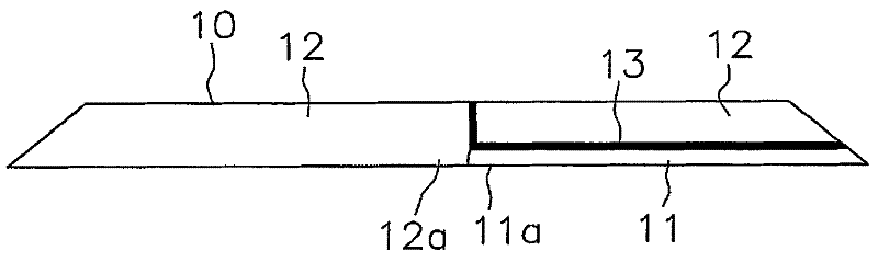
[0053] (1) In the above-mentioned embodiment, the example in which the buffer rubber 13 is provided on both sides of the tread width direction is shown, but as image 3 As shown, it may be provided only on one side in the tread width direction. Even in this case, since the top rubber 12 has a penetrating portion 12a penetrating from the ground contact surface to the bottom surface of the tread rubber 10 in the central region, the effect of maintaining the tire transverse shear rigidity as described above can be obtained. Additionally, in this embodiment, with figure 2 It is also possible to set the base rubber 11 on the other side in the tread width direction in the same way, and then with the following Figure 4 Similarly, the buffer rubber 13 may be provided on the inner periphery of the base rubber 11 .

[0054] In this configuration, it is preferable that the shoulder area on the side where the cushion rubber 13 is provided ( image 3 The right shoulder area of ​​the t...

Embodiment

[0058] Next, examples that specifically show the configuration and effects of the present invention will be described. The tires used for the evaluation are as follows: the tire model is 205 / 55R16, the air pressure is 220 kPa, and the rim model is 16×6.5-JJ. Each evaluation item was evaluated as follows.

[0059] (1) Wet braking performance

[0060] The vehicle was driven on a wet road, and the braking distance when the driving speed decreased from 100 km / h to 0 km / h was measured, and evaluated using an index when the result of Comparative Example 1 was set to 100. The smaller the value, the shorter the braking distance, indicating better wet performance.

[0061] (2) wear performance

[0062] After running for 8000 km, the difference in height between the step-in side and the kick-out side of the blocks provided in the shoulder region (the amount of zigzag wear) was measured and evaluated using the index when the result of Comparative Example 1 was set to 100. The smaller...


PUM


Abstract

A pneumatic tire (T) has a tread rubber (10) provided in a tread portion (3). The tread rubber (10) comprises a cap rubber (12) which forms a contact surface, a base rubber (11) arranged in an inner peripheral side of the cap rubber (12), and a cushion rubber (13) formed by a rubber having a smaller storage elastic modulus E' than the cap rubber (12) and the base rubber (11). The cap rubber (12) has a penetration portion (12a) which reaches a bottom surface of the tread rubber (10) from the contact surface in a center region. The base rubber (11) is terminated by the penetration portion (12a). The cushion rubber (13) extends from a side surface of the tread rubber (10) toward the center region along the base rubber (11), and bends to an outer peripheral side from a portion near a terminating portion (11 a) of the base rubber (11) so as to reach the contact surface.

Description

technical field [0001] The present invention relates to a pneumatic tire capable of improving wet braking performance without impairing wear performance and handling stability. Background technique [0002] It is well known that among methods of improving braking performance on wet roads (hereinafter referred to as wet braking performance), there is a method of obtaining a good braking effect by increasing the tan δ value (loss tangent value) of the tread rubber. Additionally, if Figure 10 As shown, the tanδ value is dependent on the strain. It can be said that the wet braking performance is controlled by the shear strain in the front and rear direction of the tire produced by the tread rubber during braking, and the corresponding tanδ value. However, conventional tires have difficulty in controlling the shear strain generated during braking as shown below, and thus have room for improvement. [0003] That is, in a tread rubber having a laminated structure of a cap rubber ...

Claims


Application Information

Patent Timeline
Patent Type & Authority Applications(China)
IPC IPC(8): B60C11/00B60C9/02
CPCB60C11/005B60C2011/0025B60C11/00B60C11/0058B60C11/0075Y10T152/10495
Inventor 濑川政弘
Owner TOYO TIRE & RUBBER CO LTD
Why Eureka
Try Eureka