Balloon dilatation catheter

A technology for dilating catheters and balloons, applied in balloon catheters, catheters, dilators, etc., can solve problems such as bending deformation, insufficient catheter pushing force, insufficient pushing force, etc., to reduce the cross-sectional area, avoid blood vessel damage, The effect of avoiding secondary damage

Active Publication Date: 2012-06-20
SHANGHAI VASOLUTIONS MEDTECH CO LTD
View PDF6 Cites 18 Cited by
  • Summary
  • Abstract
  • Description
  • Claims
  • Application Information

AI Technical Summary

Problems solved by technology

[0003] Most of the existing balloon dilatation catheters are composed of polymer materials. During use, if a long diffuse lesion is encountered, especially a lesion with severe calcification, the coaxial balloon dilation catheter is often pushed by the catheter. Insufficient force causes the balloon dilatation catheter to fail to pass through the lesion smoothly, and there is even the possibility that the catheter may be broken in the blood vessel, which affects the operation process and may even cause potential danger to the patient; for the rapid exchange structure of the balloon dilation catheter In other words, due to insufficient pushing force, it is difficult to pass long and short lesions, so the applicable objects are limited
In addition, for those coaxial balloon dilatation catheters that directly use the entire metal reinforced tube, due to the integrity and strong bending resistance of the metal reinforced tube, the blood vessel will be forcibly straightened in the early stage of use. After use, the balloon dilation catheter is often difficult to withdraw due to the irreversible bending deformation of the metal tube, and at the same time causes secondary damage to the vessel wall, which not only affects the operation process, but also brings pain to the patient. greater psychological pressure and pain

Method used


Image

  • Balloon dilatation catheter
  • Balloon dilatation catheter
  • Balloon dilatation catheter

Examples


Embodiment Construction

[0026] In order to enable those skilled in the art to better understand the technical solutions in the present application, the technical solutions in the embodiments of the present application will be clearly and completely described below in conjunction with the drawings in the embodiments of the present application. Obviously, the described The embodiments are only some of the embodiments of the present application, but not all of them. Based on the embodiments in this application, all other embodiments obtained by persons of ordinary skill in the art without creative efforts shall fall within the scope of protection of this application.

[0027] The "distal end" in this article refers to the end close to the patient during delivery, and the "proximal end" refers to the end close to the operator during clinical manipulation.

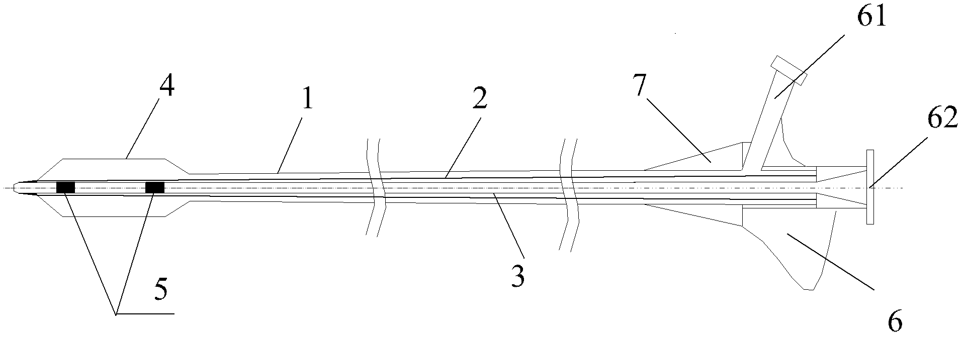
[0028] figure 1 A schematic structural view of a specific embodiment of the balloon dilatation catheter provided in this application.

[0029] Such...


PUM


Abstract

The invention discloses a balloon dilatation catheter, which comprises an outer tube, a reinforced tube, a balloon, an inner tube and a connector, wherein the reinforced tube penetrates through an inner cavity of the outer tube, a far end of the reinforced tube penetrates through the balloon and is hermetically fixed to a far end of the balloon, the reinforced tube is provided with a plurality of hollowed-out grooves, the inner tube penetrates through an inner cavity of the reinforced tube, a far end of the inner tube extends out of the far end of the reinforced tube and is hermetically fixed to the balloon, and the connector is fixed to a near end of the outer tube and provided with a first joint and a second joint. Compared with an existing integral reinforced tube, the balloon dilatation catheter not only can automatically and flexibly change bending angles according to practical bending of a blood vessel to fit the bending and changeable blood vessel and avoid damaging the blood vessel due to forcedly straightening the blood vessel, but also can avoid secondary damage to the blood vessel caused by pullback of the catheter with irreversible bending deformation after being acted by external force, and is beneficial to a blood vessel dilatation surgery.

Description

technical field [0001] The present application relates to the technical field of medical devices, in particular to a balloon dilatation catheter. Background technique [0002] Balloon dilatation catheter is a tool for endovascular angioplasty, which has been widely used in clinical medicine of percutaneous transluminal angioplasty and percutaneous transluminal angioplasty. Under the guidance of appropriate imaging equipment, the balloon dilation catheter is pushed to the stenotic part of the blood vessel through percutaneous puncture technology, and the balloon is expanded under strict monitoring, so that the stenotic part of the blood vessel is expanded, so as to achieve recovery The inner diameter of the lumen, the purpose of improving blood circulation. [0003] Most of the existing balloon dilation catheters are composed of polymer materials. During use, if long-segment diffuse lesions are encountered, especially those with severe calcification, the coaxial balloon dila...

Claims


Application Information

Patent Timeline
Patent Type & Authority Applications(China)
IPC IPC(8): A61M29/02A61M25/10A61F2/958
CPCA61M25/1006A61M29/02A61F2/958A61M25/10A61M25/0054A61M25/0051A61M25/104
Inventor 谢志永孙芳华李孝秀卢惠娜张滢涛朱佳英宋林飞郭芳罗七一
Owner SHANGHAI VASOLUTIONS MEDTECH CO LTD
Why Eureka
Try Eureka