Multichannel fluorescence test system and method of water concentration field

A technology for testing systems and concentration fields, applied in the field of multi-channel fluorescence testing systems and methods for concentration fields in water areas, can solve problems such as difficult application and expensive laser light sources, and achieve the effects of low cost, accurate concentration parameters, and simple structure

Active Publication Date: 2013-12-11
CHINA INST OF WATER RESOURCES & HYDROPOWER RES +1
View PDF10 Cites 0 Cited by
  • Summary
  • Abstract
  • Description
  • Claims
  • Application Information

AI Technical Summary

Problems solved by technology

The laser light source is very expensive, and it is difficult to apply in the detection of large-area concentration fields

Method used


Image

  • Multichannel fluorescence test system and method of water concentration field
  • Multichannel fluorescence test system and method of water concentration field
  • Multichannel fluorescence test system and method of water concentration field

Examples


Embodiment 1

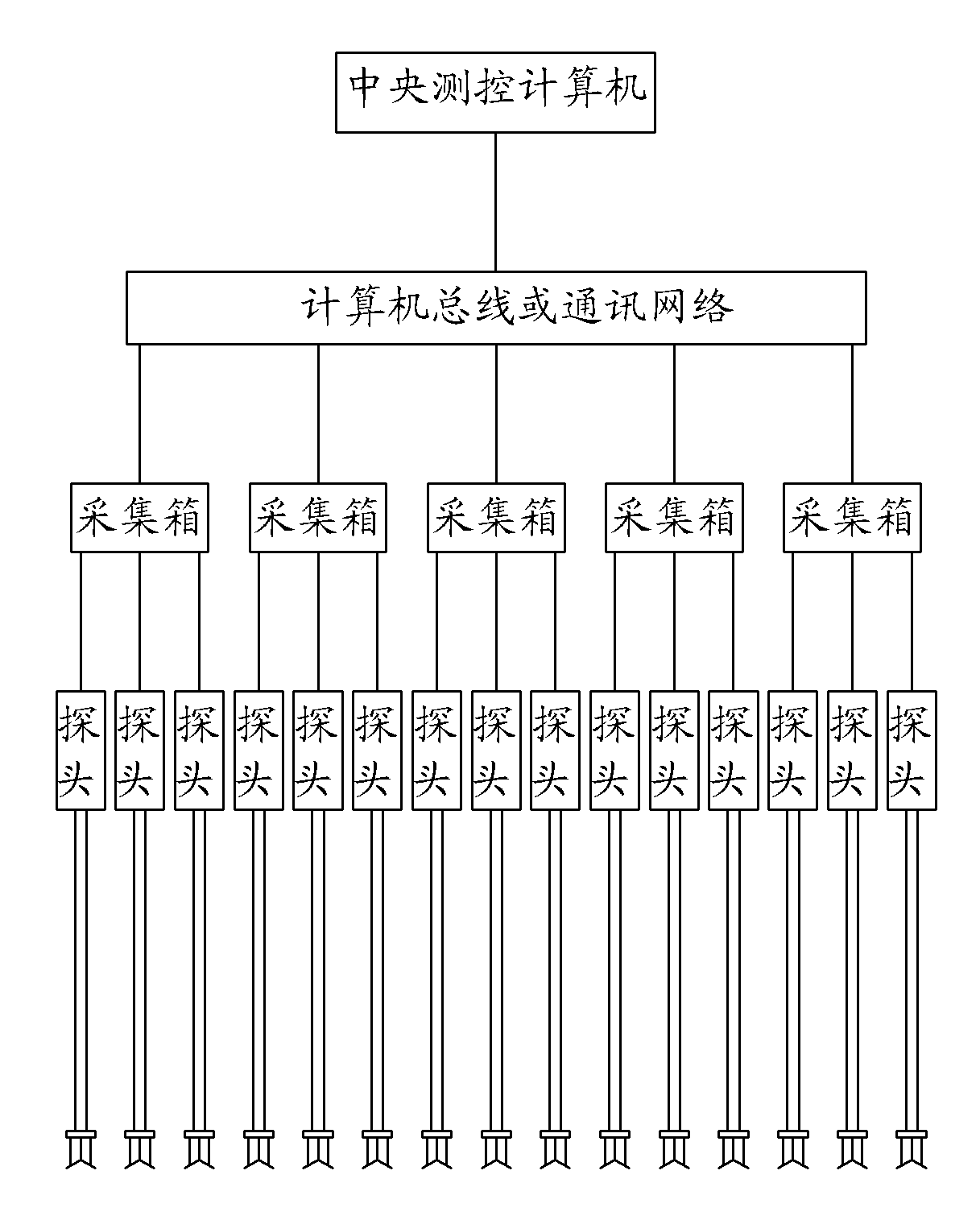
[0031] This embodiment is a multi-channel fluorescence test system for water concentration field, such as figure 1 shown. This embodiment includes: the tracer dropped in the waters, and each detection point in the waters is provided with a probe group composed of a plurality of probes, the probes are connected to the collection box through a shielded cable, and the collection box is connected by a computer The bus or communication network is connected to the central measurement and control computer installed with acquisition and calibration software. The probe includes an LED tube that excites the tracer to generate fluorescence, and a photocell that receives the fluorescence. figure 1 The system shown is a schematic of five acquisition boxes with three probes connected to each acquisition box. In this embodiment, up to 10 or more collection boxes can actually be connected, and each collection box can be connected with 24 or more probes.

[0032] The waters described in this...

Embodiment 2

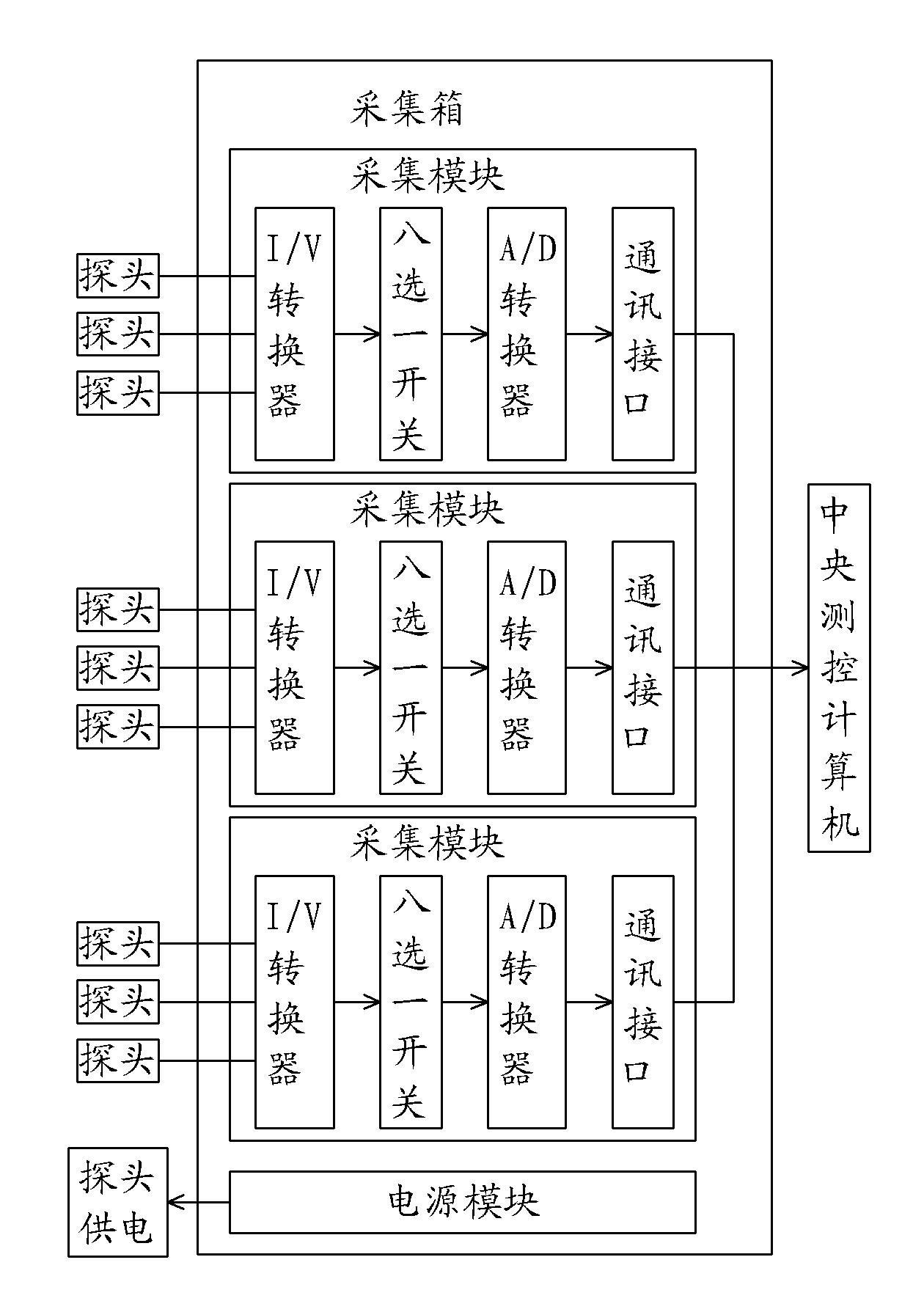
[0046] This embodiment is an improvement of Embodiment 1, and it is a refinement of the collection box in Embodiment 1. The principle is as follows figure 2 shown. The acquisition box described in this embodiment is provided with a power supply module, a communication interface and a plurality of acquisition modules, and the acquisition module contains an I / V converter connected to the probe, and the I / V converter is sequentially selected with one of eight Switches, A / D converters, and communication interface connections.

[0047] The acquisition box described in this embodiment is a key intermediate link between the probe and the central measurement and control computer. Each collection box can be equipped with multiple collection modules and a power supply module, figure 2 There are three acquisition modules in the figure, and more acquisition modules can be installed in actual implementation. The power supply module provides constant voltage power for each connected p...

Embodiment 3

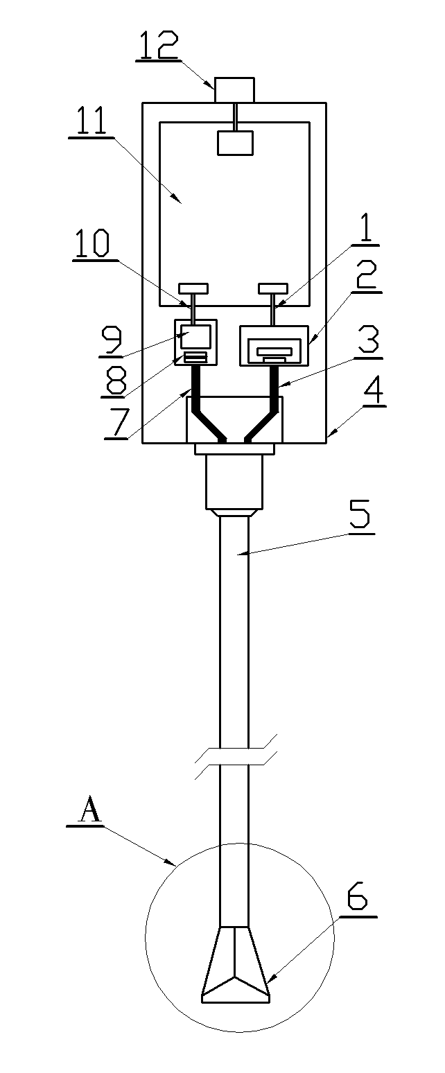
[0049] This embodiment is an improvement of Embodiments 1 and 2, and it is a refinement of the probe in Embodiments 1 and 2. The structure is as follows image 3 shown. The probe described in this embodiment includes: a box body 4, in which an LED tube 2 and a photocell 9 are installed and connected to a signal circuit board 11, and the signal circuit board is connected to the collection box through a connector 12. The light-incoming side of the photocell is provided with a filter group 8, and the receiving light fiber bundle 7 is arranged in front of the filter group, and the excitation light fiber bundle 3 is arranged on the light-emitting side of the LED tube. The optical fiber bundle and the excitation light optical fiber bundle are placed in the probe rod tube 5 , and the end of the probe rod tube is connected with the isolation cap 6 . The LED tube is electrically connected with the modulator and the constant current source, and the constant current source is electrical...


PUM

PropertyMeasurementUnit
wavelengthaaaaaaaaaa
emission peakaaaaaaaaaa

Abstract

The invention relates to multichannel fluorescence test system and method of a water concentration field. Adopting the principle (LIF) (laser induced fluorescence) that a tracer can generate fluorescence under the irradiation of a specific light source, the system includes: a tracer, fluorescein sodium, put in a water area, and probe groups set at each detecting spot in the water area. The probes are connected to collection boxes through shield cables, and the collection boxes are then connected to a central measurement and control computer equipped with collection and calibration software through a computer bus or communication network for conducting sampling, analysis and display on the tracer concentration of discharged sewage in a large water area. The important components, probes, include LEDs (light-emitting diodes) irradiating water currents containing the tracer, and photocells for receiving excited fluorescence in the water. The system and method of the invention fill the gap in the detection field of pollutant concentration fields in large water physical model experiments, and are also effective means for field observation of water pollution.

Description

technical field [0001] The invention relates to a multi-channel fluorescent test system and method for concentration field in water area, which is a test system and method for optical and electronic detection of tracer concentration field in large area water area by using bus technology or communication network technology. Background technique [0002] It is more and more important to test the concentration of a certain substance in a large area concentration field in modern water environment protection research. For example, if a possible pollution source appears at a certain location in a river basin, how to judge the pollution impact of this pollution source on the downstream basin requires an understanding of the concentration field of the hydrodynamic dilution of pollutants in the affected river section. The research method can adopt the method of setting the test system in the river section model of the physical model; it can also use the test system to conduct prototy...

Claims


Application Information

Patent Timeline
Patent Type & Authority Patents(China)
IPC IPC(8): G01N21/64
Inventor 樊宜贺益英杨楠谭水位朱杰斌李昌垣吴一红李荣方许新发张强孙淑卿熊丽萍易建洲
Owner CHINA INST OF WATER RESOURCES & HYDROPOWER RES
Why Eureka
Try Eureka