Multichannel fluorescence test system and method of water concentration field
A testing system and a concentration field technology, which are applied in the field of multi-channel fluorescence testing systems and methods for water concentration fields, can solve the problems of expensive and difficult application of laser light sources, and achieve the effects of low cost, solving detection problems and simple structure.
- Summary
- Abstract
- Description
- Claims
- Application Information
AI Technical Summary
Problems solved by technology
Method used
Image
Examples
Embodiment 1
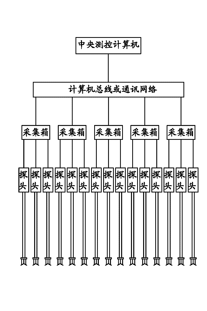
[0031] This embodiment is a multi-channel fluorescence test system for water concentration field, such as figure 1 shown. This embodiment includes: the tracer dropped in the waters, and each detection point in the waters is provided with a probe group composed of a plurality of probes, the probes are connected to the collection box through a shielded cable, and the collection box is connected by a computer The bus or communication network is connected to the central measurement and control computer installed with acquisition and calibration software. The probe includes an LED tube that excites the tracer to generate fluorescence, and a photocell that receives the fluorescence. figure 1 The system shown is a schematic of five acquisition boxes with three probes connected to each acquisition box. In this embodiment, up to 10 or more collection boxes can actually be connected, and each collection box can be connected with 24 or more probes.
[0032] The waters described in this...
Embodiment 2
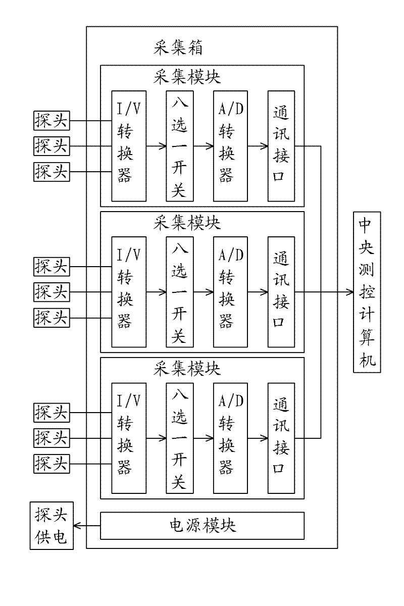
[0046] This embodiment is an improvement of Embodiment 1, and it is a refinement of the collection box in Embodiment 1. The principle is as follows figure 2 shown. The acquisition box described in this embodiment is provided with a power supply module, a communication interface and a plurality of acquisition modules, and the acquisition module contains an I / V converter connected to the probe, and the I / V converter is sequentially selected with one of eight Switches, A / D converters, and communication interface connections.
[0047] The acquisition box described in this embodiment is a key intermediate link between the probe and the central measurement and control computer. Each collection box can be equipped with multiple collection modules and a power supply module, figure 2 There are three acquisition modules in the figure, and more acquisition modules can be installed in actual implementation. The power supply module provides constant voltage power for each connected p...
Embodiment 3
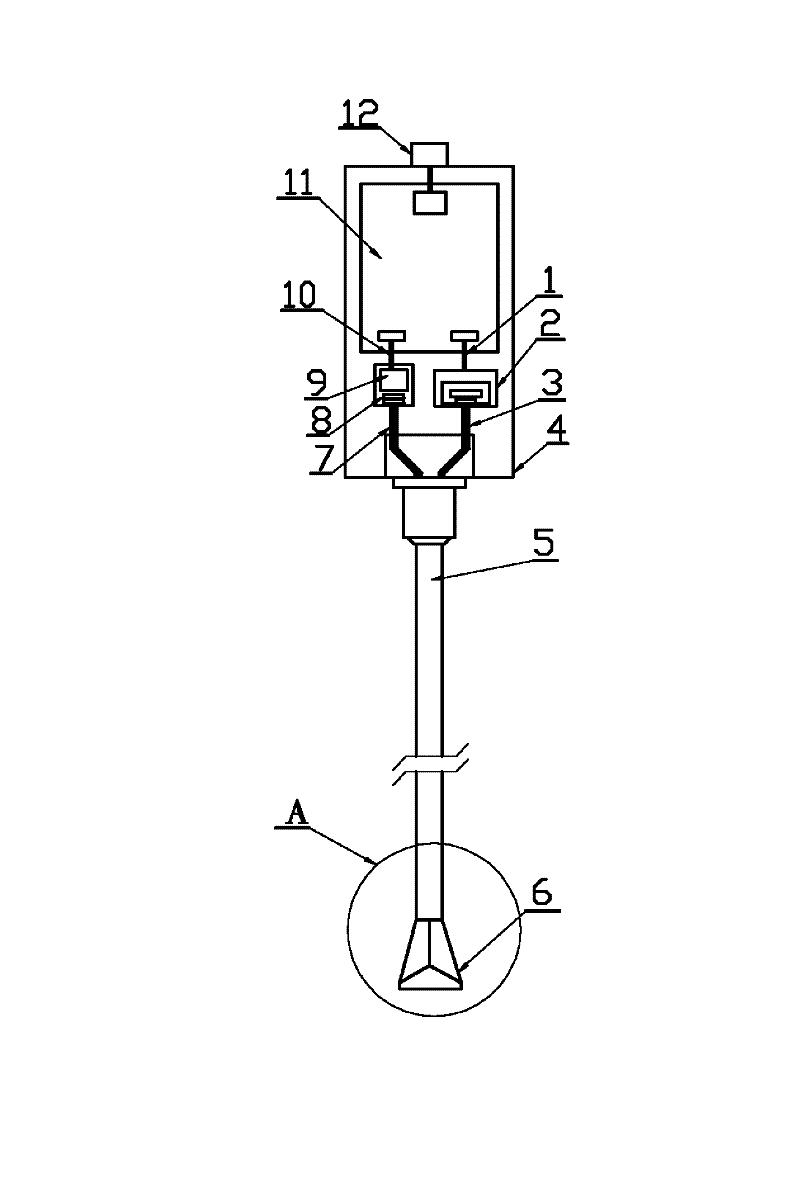
[0049] This embodiment is an improvement of Embodiments 1 and 2, and it is a refinement of the probe in Embodiments 1 and 2. The structure is as follows image 3 shown. The probe described in this embodiment includes: a box body 4, in which an LED tube 2 and a photocell 9 are installed and connected to a signal circuit board 11, and the signal circuit board is connected to the collection box through a joint 12. The light-incoming side of the photocell is provided with a filter group 8, and the receiving light fiber bundle 7 is arranged in front of the filter group, and the excitation light fiber bundle 3 is arranged on the light-emitting side of the LED tube. The optical fiber bundle and the excitation light optical fiber bundle are placed in the probe rod tube 5 , and the end of the probe rod tube is connected with the isolation cap 6 . The LED tube is electrically connected with the modulator and the constant current source, and the constant current source is electrically c...
PUM
 Abstract
Description
Claims
Application Information
 - R&D
- Intellectual Property
- Life Sciences
- Materials
- Tech Scout
- Unparalleled Data Quality
- Higher Quality Content
- 60% Fewer Hallucinations
Browse by: Latest US Patents, China's latest patents, Technical Efficacy Thesaurus, Application Domain, Technology Topic, Popular Technical Reports.
© 2025 PatSnap. All rights reserved.Legal|Privacy policy|Modern Slavery Act Transparency Statement|Sitemap|About US| Contact US: help@patsnap.com


