Insulator with temperature monitoring function
A technology of insulators and functions, applied in thermometers, insulators, thermometers with physical/chemical changes, etc., can solve the problems of high manufacturing cost, due maintenance, and heavy workload of optical fiber sensors, so as to improve implementability and reliability Enhanced performance and low manufacturing cost
- Summary
- Abstract
- Description
- Claims
- Application Information
AI Technical Summary
Problems solved by technology
Method used
Image
Examples
Embodiment 1
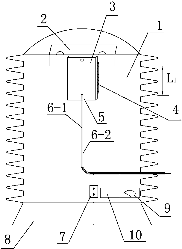
[0020] Embodiment 1: as figure 1 As shown, the present embodiment has an upright post-type insulator 1 and an insulator base 8 arranged at the lower end of the insulator. A conductive metal strip 2 is arranged on the upper end of the insulator 1, and the lower side of the conductive metal strip 2 is connected to a thermally conductive insulating strip 3 (English name the insulation heat conduction hereinafter referred to as IHC) embedded in the insulator 1. The thermally conductive insulating strip is in the shape of a rectangular sheet . In order to prevent the heat from being dissipated and improve the precision and accuracy of the measurement, insulating heat shields 4 of the same shape are clamped on both sides of the heat conducting insulating strip 3 . The lower end (non-electric side) of the heat-conducting insulating strip 3 is equipped with a temperature measuring device 5 . The temperature measuring device 5 is electrically connected to the temperature measuring wi...
Embodiment 2
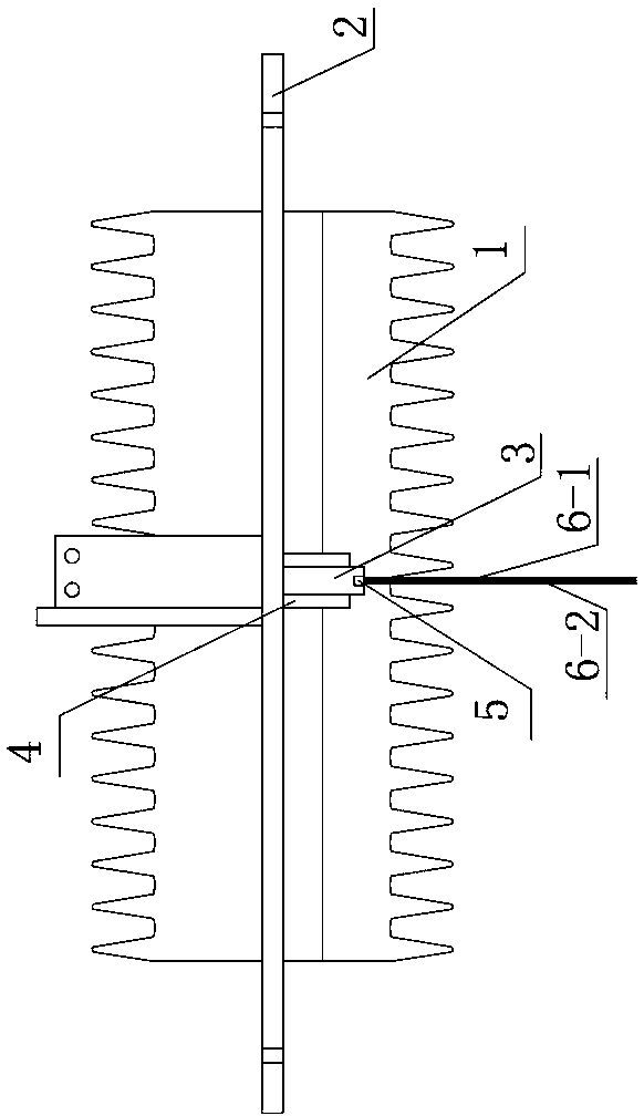
[0026] Embodiment 2: as figure 2 As shown, the structure of this embodiment is basically the same as that of Embodiment 1, except that this embodiment has a wall-piercing bushing insulator 1 and a conductive metal strip 2 that penetrates the insulator 1 axially and is embedded in the insulator. The middle (or both ends) of the bar 2 is connected to the heat-conducting insulating bar 3 with insulating and heat-shielding boards 4 on both sides. ) is led to the outside of the insulator through the temperature measuring line 6-1 covered with an insulating sheath 6-2, and the outlet of the temperature measuring line 6-1 is equipped with a wired communication terminal, and the temperature signal can be transmitted to the remote control receiver through a wired method center.
[0027]In this example, the material of the insulator can be ceramic filled quartz powder cement type, epoxy resin (indoor type) or unsaturated polyester fiberglass (outdoor type). The thermally conductive i...
Embodiment 3
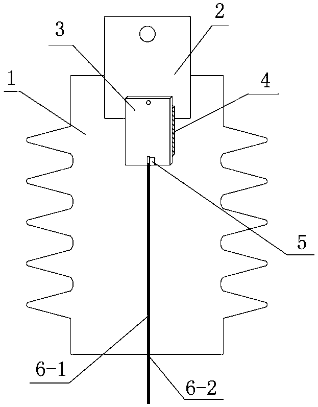
[0028] Embodiment 3: as image 3 As shown, the basic structure of this embodiment is basically the same as that of Embodiment 2, the difference is that this example is a cable joint sleeve-shaped insulator 1, and the top of the insulator 1 is vertically equipped with a conductive metal strip 2, and the lower end of the conductive metal strip is connected to the buried The heat-conducting insulating strip 3 in the insulator, the non-electric side of the heat-conducting insulating strip is equipped with a temperature measuring device 5 and a temperature measuring line 6-1 covered with an insulating sheath 6-2, and the temperature measuring line is laid along the center of the insulator and at the bottom of the insulator lead out.
[0029] This embodiment is mainly applied to temperature measurement at transformer joints or circuit breaker joints, or for temperature measurement at cable terminal joints. The insulator is generally made of silicone rubber material, which is elasti...
PUM
| Property | Measurement | Unit |
|---|---|---|
| breakdown field strength | aaaaa | aaaaa |
| flexural strength | aaaaa | aaaaa |
Abstract
Description
Claims
Application Information
 - R&D Engineer
- R&D Manager
- IP Professional
- Industry Leading Data Capabilities
- Powerful AI technology
- Patent DNA Extraction
Browse by: Latest US Patents, China's latest patents, Technical Efficacy Thesaurus, Application Domain, Technology Topic, Popular Technical Reports.
© 2024 PatSnap. All rights reserved.Legal|Privacy policy|Modern Slavery Act Transparency Statement|Sitemap|About US| Contact US: help@patsnap.com


