Scanning close-range photogrammetry method

A measurement method and close-range photography technology, applied in photogrammetry/video metrology, surveying devices, surveying and navigation, etc., can solve the problems of low intersection accuracy, difficulty in engineering applications, and inability to organize photographic data, etc.

Active Publication Date: 2012-07-18
WUHAN UNIV
View PDF5 Cites 11 Cited by
  • Summary
  • Abstract
  • Description
  • Claims
  • Application Information

AI Technical Summary

Problems solved by technology

[0010] At present, most close-range photogrammetry uses "parallel photogrammetry", and its intersection angle can only reach , which is far from meeting the requirements of photogrammetric intersection angle; if "intersection photogrammetry" is used, although it can meet the requirements of photogrammetric intersection angle, it is impossible to organize photogrammetric data for photogrammetry of large scene objects
[0011] In the existing technology, many close-range photogrammetry systems use the method of multi-baseline intersection photography to solve the contradiction between the difficulty of automatic matching when the intersection angle is large and the low accuracy of intersection angles when the intersection angle is small, but this method has many limitations , it is difficult to achieve engineering applications: the range of objects that can be photographed by one multi-baseline intersection photography is limited. control points to ensure the splicing accuracy between regions, which increases the workload in the field and limits the efficiency of data processing

Method used


Image

  • Scanning close-range photogrammetry method
  • Scanning close-range photogrammetry method
  • Scanning close-range photogrammetry method

Examples


Embodiment Construction

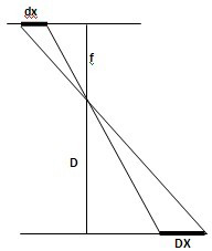
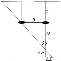
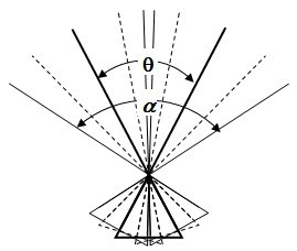
[0062] The scanning close-range photogrammetry method provided by the present invention adopts a common non-measurement digital camera (objective lenses with different focal lengths can be arbitrarily replaced according to the distance of the object to be photographed) to be placed on the scanning photography platform to perform scanning photography (while rotating the camera) photography) method, the photography distance is from tens of meters to more than 1,000 meters, and high-precision measurement of large scenes can be obtained.

[0063] According to the distance of the subject and the focal length of the camera objective lens, the method divides the scene of the subject into different "blocks" (BLOCK), that is, scene blocks. Set the corresponding basic stations (the front and rear camera stations of each BLOCK), the number of basic stations is equal to the number of "blocks" divided by the object plus one; in order to reduce the difficulty of automatic image matching caus...


PUM


Abstract

The invention relates to a scanning close-range photogrammetry method, which is used for carrying out scanography by arranging an ordinary non-measurement digital camera on a scanography tripod head. The scene of a photographed target is divided into different blocks according to the distance of the photographed target and the focal length of the objective lens of the camera, corresponding base stations are arranged, and the number of the base stations is equal to the sum of the number of the divided blocks of the target and one; in order to reduce the difficulty in automated image matching arising from the deformation of the image of the photographed target, additional stations are additionally arranged among the base stations; and the scanography is carried out on a targeted object block through horizontally and vertically rotating the camera at each photographing station. According to the scanning close-range photogrammetry method, the photographing visual field angles of the photographing stations are increased, the acquired image data simultaneously meets the requirements on measurement accuracy and matching automation, the overall processing of all image data in a photographed area can be realized by using the classic aerial triangulation theory, and the high-accuracy measurement results can be obtained at a photographing distance from tens of meters to more than one thousand meters, so that the requirements on the measurement of large-scale scene targets can be met.

Description

Technical field [0001] The invention involves photography measurement and remote sensing, especially digital close -up photography measurement and its application in engineering measurement, a method of scanning close -up photography measurement. Background technique [0002] The measurement accuracy of the photography measurement depends on the two basic parameters: [0003] ① figure 1 The plane accuracy of photography measurement depends on the size of the ground element The smaller the GSD, the higher the accuracy of the plane measurement.But GSD depends on the element Size, photography distance Photography focal length The [0004] [0005] Among them, Pacific Yuan The size is a fixed parameter for a digital camera; Distance from photography Positive, proportional, The larger, the larger the GSD, the greater the measurement error, and the photography distance Depending on the object of photography, it is often limited by the scene (generally cannot be changed valu...

Claims


Application Information

Patent Timeline
Patent Type & Authority Applications(China)
IPC IPC(8): G01C11/00
Inventor 张祖勋柯涛郑顺义黄山
Owner WUHAN UNIV
Why Eureka
Try Eureka