Gradual vapouration type high-energy-efficiency direct-flow steam injection boiler and method

A high-energy-efficiency, steam-injection technology, which is applied to steam boilers, mining fluids, steam generation, etc., can solve problems such as high flue gas temperature, burning and bursting tubes, and energy waste, so as to improve heat utilization, reduce equipment costs and Operating cost and the effect of reducing the probability of pipe burst

Inactive Publication Date: 2014-07-02
JUNMA PETROLEUM EQUIP MFG +1
View PDF6 Cites 0 Cited by
  • Summary
  • Abstract
  • Description
  • Claims
  • Application Information

AI Technical Summary

Problems solved by technology

This principle defect of the traditional steam injection boiler forces it to have extremely strict requirements on the water quality and the flame profile of the burner. If the water quality is not up to standard or the flame profile changes slightly during operation, it will easily lead to fouling of the furnace tube or even burning and bursting of the tube. wait for the accident
On the other hand, due to the limitation of the working principle of the traditional steam injection boiler, the temperature of the flue gas discharged is high, and a large amount of heat energy is lost with the flue gas discharged into the atmosphere, resulting in energy waste and environmental pollution

Method used


Image

  • Gradual vapouration type high-energy-efficiency direct-flow steam injection boiler and method
  • Gradual vapouration type high-energy-efficiency direct-flow steam injection boiler and method
  • Gradual vapouration type high-energy-efficiency direct-flow steam injection boiler and method

Examples


Embodiment Construction

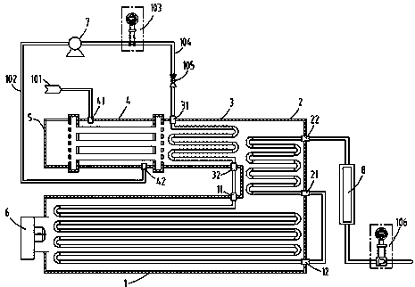
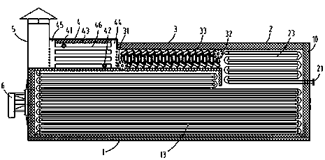
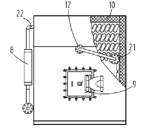
[0028] refer to figure 1 , figure 2 , image 3 , the present invention provides a slow-vaporization high-efficiency once-through steam injection boiler, which is mainly composed of four modules and accessories, wherein the four modules are: radiation water cooling module 1, slow vaporization module 2, water pipe convection module 3 and smoke pipe Water bath module 4; accessories mainly include: chimney 5, burner 6, high-pressure water pump 7, sampling separator 8, maintenance manhole 9, furnace body insulation 10, low-pressure water flow pipeline 102, water flow throttling component 103, high-pressure water vapor flow Pipeline 104, check valve 105, steam flow throttling assembly 106, instrumentation and electric control system, etc.

[0029] The radiant water cooling module 1 adopts a square membrane water cooling wall 13 structure, and is placed horizontally at the bottom of the boiler center. The gradual vaporization module 2 is designed as a square bend structure, a...


PUM


Abstract

The invention relates to a gradual vapouration type high-energy-efficiency direct-flow steam injection boiler and a method. The technical scheme of the invention is that the steam injection boiler mainly consists of four modules and an accessory, wherein the four modules comprise a radiation water-cooled module, a gradual vapouration module, a water pipe convection module and a smoke pipe water bath module; the radiation water-cooled module is placed on the bottom of the center of the boiler in a horizontal manner, a front-end opening of the water-cooled module is butted with a burner, and a tail-end upper opening is connected with the bottom of the gradual evapouration module; a front-side opening in the horizontal direction of the gradual vapouration module is connected with the water pipe convection module, and the rear side of the water pipe convection module is connected with the smoke pipe water bath module by a front smoke box; and the smoke pipe water bath module is of a square structure, and is connected with a chimney by a rear smoke box. The boiler and the method have the beneficial effects of preventing a heat transmission exacerbation phenomenon from being generated from fundamentality, greatly reducing tube exploding probability, promoting safety and stability, solving the problem that the heat transmission exacerbation easily exists in a large specific heat region under supercritical pressure, and the energy is saved and the consumption is reduced so as to be beneficial for environmental protection.

Description

technical field [0001] The invention relates to a special equipment for heavy oil exploitation by steam injection thermal power in the petroleum industry, in particular to a gradual vaporization high-energy-efficiency direct current with the principle of gradual vaporization in the convection area, the principle of preheating water supply in the smoke pipe water bath, and low smoke temperature emission. Steam injection boiler and method. Background technique [0002] At present, the general principle of steam injection boilers at home and abroad is: the softened water enters the casing water-water heat exchanger after being boosted by a high-pressure plunger, so that the water temperature is higher than the "dew point" temperature of the flue gas (the water temperature is usually about 110-120°C , to prevent the flue gas from corroding the furnace tube due to the acid water condensed due to low temperature), the water then enters the flue gas convection area to absorb he...

Claims


Application Information

Patent Timeline
Patent Type & Authority Patents(China)
IPC IPC(8): F22B31/08F22D1/02E21B43/24
Inventor 王玉庆闫继超马宗赛段明涛杨乐李文军王海峰
Owner JUNMA PETROLEUM EQUIP MFG
Why Eureka
Try Eureka