Laser processing machine and bellows device

A laser processing machine, accordion technology, applied in auxiliary devices, laser welding equipment, metal processing equipment, etc., can solve problems such as damage, carbonization of accordion folds, openings, etc.

Active Publication Date: 2015-04-15
MITSUBISHI ELECTRIC CORP
View PDF9 Cites 0 Cited by
  • Summary
  • Abstract
  • Description
  • Claims
  • Application Information

AI Technical Summary

Problems solved by technology

[0003] If the optical path is shifted for some reason, or the bellows is bent, and the laser light is reflected on the workpiece and irradiated to the accordion surface, the bellows may be carbonized (burned) and damaged, and start hole
In addition, when the molten material (splash) generated during laser processing splashes and adheres to the bellows, the bellows may be carbonized and damaged.

Method used


Image

  • Laser processing machine and bellows device
  • Laser processing machine and bellows device
  • Laser processing machine and bellows device

Examples


Embodiment approach 1

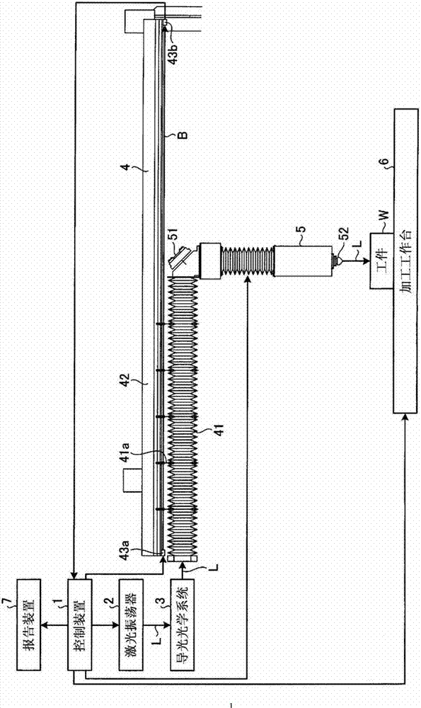
[0041] figure 1 It is a figure which shows the structure of Embodiment 1 of the laser processing machine concerning this invention. The laser processing machine includes a control device 1 , a laser oscillator 2 , a light guide optical system 3 , a bellows folding device 4 , a processing head 5 , a processing table 6 and a reporting device 7 . The laser processing machine propagates the laser light L emitted from the laser oscillator 2 along a predetermined optical path, and guides it to the workpiece W on the processing table 6 .

[0042] Laser oscillator 2 is CO 2 A device such as a laser that oscillates the laser light L emits the laser light L while varying the laser power during laser processing.

[0043] The light guide optical system 3 includes the following optical components not shown in the figure: a PR mirror, which partially reflects the laser light L emitted by the laser oscillator 2; a deflection mirror, which changes the beam of the laser light L transmitted f...

Embodiment approach 2

[0058] Figure 7 It is a figure which shows the structure of Embodiment 2 of the laser processing machine concerning this invention. The present embodiment is different from the first embodiment in that the beam sensor is provided not on the bellows movement guide 42 but on the bellows 41 .

[0059] In the present embodiment, the amount of light received by the beam sensor light receiving unit 43 b changes in accordance with the expansion and contraction of the bellows 41 , that is, the position of the processing head 5 . Therefore, the control device 1 corrects the amount of light received by the beam sensor light receiving section 43 b according to the position of the machining head 5 , and then judges the presence or absence of damage due to carbonization of the bellows 41 .

[0060] In other respects, since it is the same as that of Embodiment 1, repeated descriptions will be omitted.

[0061] In the present embodiment, since smoke can be detected over the entire length ...

Embodiment approach 3

[0063] Figure 8 It is a figure which shows the structure of Embodiment 3 of the laser processing machine concerning this invention. This embodiment differs from Embodiment 2 in that a beam sensor is provided inside the bellows 41 . That is, in the present embodiment, the light beam B emitted from the light beam sensor light emitting unit 43 a passes through the space inside the bellows 41 and reaches the light beam sensor light receiving unit 43 b.

[0064] When the reflected light from the workpiece W or the like enters the processing head 5 and irradiates the inner surface of the bellows 41, the bellows 41 is carbonized from the inside, and therefore, the smoke does not disappear until holes are opened in the bellows 41. Leaks out of the bellows 41 . Therefore, in the case where the beam sensor is provided outside the bellows 41 as in Embodiments 1 and 2 above, even if damage due to carbonization occurs inside the bellows 41 , holes cannot be opened in the bellows 41 . d...


PUM


Abstract

Provided are: a machining table (6) on which a workpiece (W) is placed, a laser oscillator (2) emitting a laser beam (L); a light-guide optical system (3) deflecting the laser beam (L) emitted from the laser oscillator (2); a cylindrical extensible bellows (41) surrounding an optical path of the laser beam (L) after the light-guide optical system (3) deflects the laser beam; a bend mirror (51) moving in an axial direction of the bellows (41) while extending or contracting the bellows (41) and deflecting the laser beam (L) having passed through the bellows (41) toward the machining table (6); a machining head (5) irradiating the workpiece (W) with the laser beam deflected by the bend mirror (51); an abnormality detector including a beam-sensor light-emitting unit (43a) emitting a light beam (B) advancing in parallel with an axis of the bellows (41) and a beam-sensor light-receiving unit (43b) measuring the amount of received light of the light beam (B); and a control device (1) bringing down the laser oscillator (2) when the amount of received light of the light beam (B) in the beam-sensor light-receiving unit (43b) falls below a first threshold.

Description

technical field [0001] The invention relates to a laser processing machine and a bellows folding device. Background technique [0002] In a laser processing machine that processes a workpiece by irradiating laser light, laser light emitted from a laser oscillator is guided onto the workpiece along a predetermined optical path. When it is necessary to make the length of the optical path variable for focusing, etc., a bellows device having a retractable cylindrical bellows is provided in the laser processing machine, and the accordion is configured so that the optical path is surrounded by the bellows, and the bellows are folded. The interior makes the laser travel. [0003] If the optical path is shifted for some reason, or the bellows is bent, and the laser light is reflected on the workpiece and irradiated to the accordion surface, the bellows may be carbonized (burned) and damaged, and start hole. In addition, when molten material (spatter) generated during laser proces...

Claims


Application Information

Patent Timeline
Patent Type & Authority Patents(China)
IPC IPC(8): B23K26/00B23K26/064B23K26/70B23K26/14
CPCB23K37/0235B23K26/0853B23K26/0869
Inventor 横井茂
Owner MITSUBISHI ELECTRIC CORP
Why Eureka
Try Eureka